

17
OPERATION OF CONTROLS
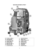
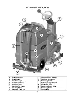
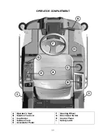
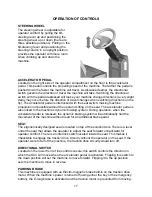
STEERING WHEEL
The steering wheel is adjustable for
operator comfort by pulling the
tilt-
steering lever
up and positioning the
steering wheel up or down (there are
three possible positions). Pulling on the
tilt-steering lever
and positioning the
steering column in an upright position
provides the operator with more room
when climbing up and down the
machine.
ACCELERATOR PEDAL
Located on the right side of the operator compartment on the floor is the accelerator
pedal. This pedal controls the propelling speed of the machine. The farther the pedal is
pushed down the faster the machine will travel. As discussed earlier, the directional
switch governs the direction of travel the machine will take. Switching the directional
switch with the pedal depressed will make your machine change directions (a very slight
delay may occur before the direction of travel changes when switching directions on the
fly). The accelerator pedal is interlocked with the seat switch, making machine
propulsion not possible without the operator sitting on the seat. The accelerator pedal is
also linked to the machine’s
dynamic braking system
. During operation, when the
accelerator pedal is released, the dynamic braking system will automatically halt the
movement of the machine without need for an additional brake pedal.
SEAT
The ergonomically designed seat is located on top of the solution tank. There is a lever
under the seat that allows the operator to adjust the seat forward or backward for
operator comfort. There is an interlock switch located inside the seat. This makes it
impossible to engage the traction drive circuitry without the operator on the seat. If the
operator were to fall off the machine, the traction drive circuitry would turn off.
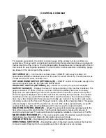
DIRECTIONAL SWITCH
Located on the lower front of the control console, this switch controls the direction in
which the SCV will move when the
accelerator pedal
is activated. Flipping this switch to
the down position will set the machine to move forward. Flipping it to the up position
sets the machine to move in reverse.
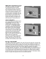
PARKING BRAKE
This machine is equipped with an
Electro-magnetic brake
built-in on the traction drive
motor. When the machine’s power is turned off (using either the key or the emergency
button), the
E-mag
brake is activated and the traction motor is prevented from moving.
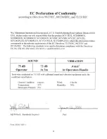
Содержание SCV 28/32
Страница 1: ...SCV 28 32 RIDER SCRUBBER OPERATION SERVICE PARTS CARE ...
Страница 3: ...3 ...
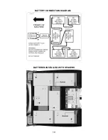
Страница 19: ...19 BATTERY CONNECTION DIAGRAM BATTERIES INSTALLED WITH SPACERS ...
Страница 34: ...34 EXPLODED VIEWS MAIN ASSEMBLY I ...
Страница 35: ...35 MAIN ASSEMBLY I BOM ...
Страница 36: ...36 MAIN ASSEMBLY II ...
Страница 37: ...37 MAIN ASSEMBLY II BOM ...
Страница 38: ...38 MAINFRAME ASSEMBLY I ...
Страница 39: ...39 MAINFRAME ASSEMBLY II ...
Страница 40: ...40 MAINFRAME ASSEMBLY II BOM ...
Страница 41: ...41 FRONT DRIVE ASSEMBLY ...
Страница 42: ...42 FRONT DRIVE ASSEMBLY BOM ...
Страница 43: ...43 STEERING ASSEMBLY ...
Страница 44: ...44 STEERING ASSEMBLY BOM ...
Страница 45: ...45 SOLUTION TANK ASSEMBLY SEAT ASSEMBLY ...
Страница 46: ...46 SOLUTION TANK ASSEMBLY SEAT ASSEMBLY BOM s ...
Страница 47: ...47 ELECTRICAL PANEL ...
Страница 48: ...48 CONSOLE ...
Страница 49: ...49 RECOVERY TANK I ...
Страница 50: ...50 RECOVERY TANK I BOM ...
Страница 51: ...51 RECOVERY TANK II ...
Страница 52: ...52 BATTERY BOX ASSEMBLY ...
Страница 53: ...53 PUMP ASSEMBLY ...
Страница 54: ...54 PUMP ASSEMBLY BOM ...
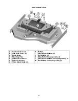
Страница 55: ...55 REAR AXLE ASSEMBLY ...
Страница 56: ...56 SQUEEGEE MECHANISM ASSEMBLY ...
Страница 57: ...57 28 REAR SQUEEGEE ASSEMBLY ...
Страница 58: ...58 28 REAR SQUEEGEE ASSEMBLY BOM ...
Страница 59: ...59 32 REAR SQUEEGEE ASSEMBLY ...
Страница 60: ...60 32 REAR SQUEEGEE ASSEMBLY BOM ...
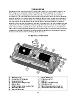
Страница 61: ...61 28 CYLINDRICAL SCRUBDECK ITEMS 1 32 ...
Страница 62: ...62 28 CYLINDRICAL SCRUBDECK ITEMS 33 64 ...
Страница 63: ...63 28 CYLINDRICAL SCRUBDECK BOM ...
Страница 64: ...64 32 CYLINDRICAL SCRUBDECK ITEMS 1 32 ...
Страница 65: ...65 32 CYLINDRICAL SCRUBDECK ITEMS 33 64 ...
Страница 66: ...66 32 CYLINDRICAL SCRUBDECK BOM ...
Страница 67: ...67 28 DISK SCRUBDECK ...
Страница 68: ...68 28 DISK SCRUBDECK BOM ...
Страница 69: ...69 32 DISK SCRUBDECK ...
Страница 70: ...70 32 DISK SCRUBDECK BOM ...
Страница 71: ...71 CYLINDRICAL SCRUBDECK SIDE SQUEEGEE LEFT SIDE ...
Страница 72: ...72 CYLINDRICAL SCRUBDECK SIDE SQUEEGEE RIGHT SIDE ...
Страница 73: ...73 DISK SCRUBDECK SIDE SQUEEGEE LEFT SIDE ...
Страница 74: ...74 DISK SCRUBDECK SIDE SQUEEGEE RIGHT SIDE ...
Страница 75: ...75 CYLINDRICAL SCRUBDECK AND ROLLER BUMPER MOUNTING ...
Страница 76: ...76 SCV28CQP SCV32CQP BOM s ...
Страница 77: ...77 DISK SCRUBDECK AND ROLLER BUMPER MOUNTING ...
Страница 78: ...78 SCV28DQP SCV32DQP BOM s ...
Страница 79: ...79 PLUMBING DIAGRAM ...
Страница 80: ...80 WIRING DIAGRAMS TRIO CONNECTIONS ...
Страница 81: ...81 P3 TRIO CONNECTIONS ...
Страница 82: ...82 P2 TRIO CONNECTIONS ...
Страница 83: ...83 WIRE COLORS CODES ...