citors that discharge through the coils of
the combination magnets. C6 discharges
through the coil of the mirror-release
combination magnet M1; C5 discharges
through the coil of the diaphragm-control
combination magnet M2.
As yet, you can't reach the combina
tion magnets. So, if there's a problem in
either the mirror-release circuit or in the
diaphragm-control circuit, you may have
to remove the front-plate assembly.
However, you can troubleshoot both cir
cuits and pinpoint the malfunction w ith
o u t further disassembly. And, if you find
that the problem is on the circuit board,
Fig. 8, you can make the repair w itho u t
disassembling the camera any further.
The tw o combination magnets have
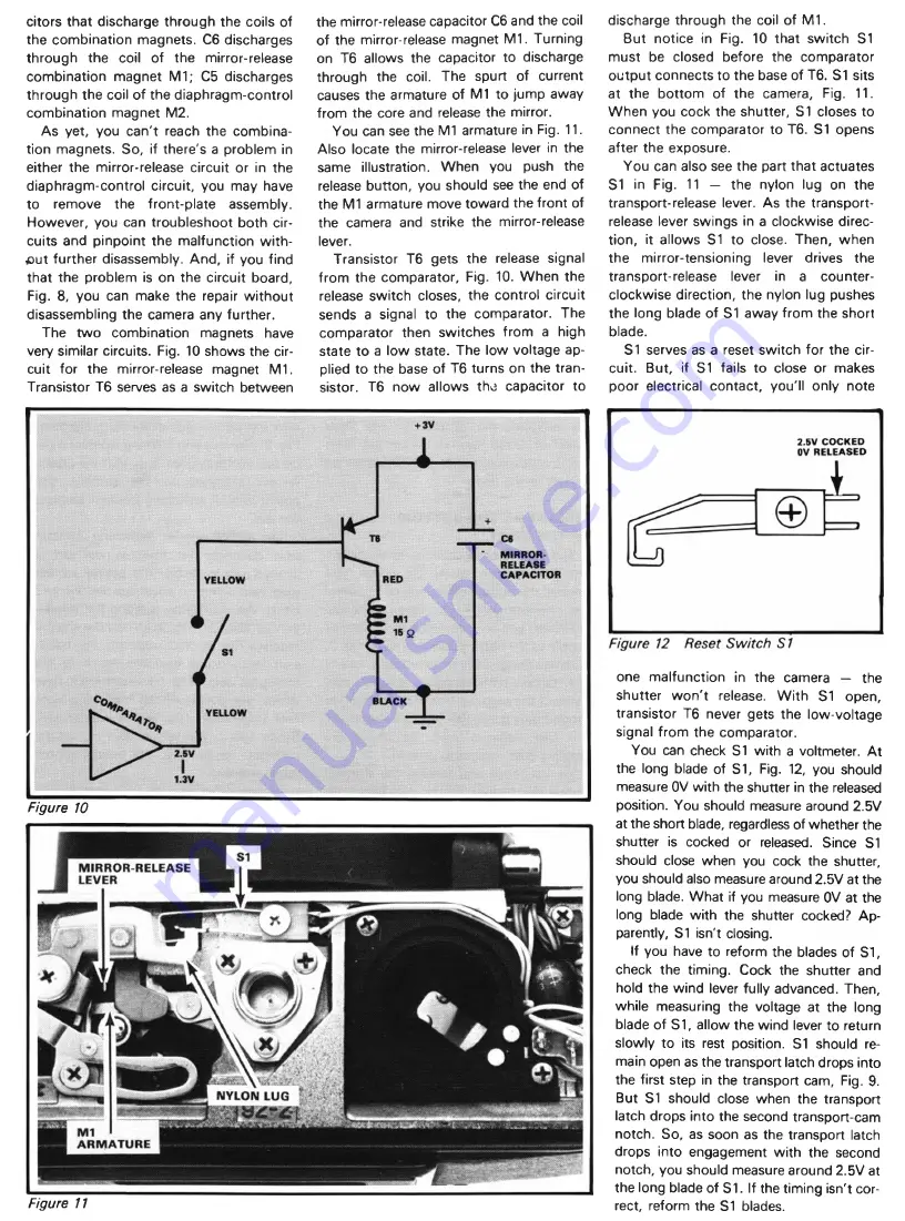
very similar circuits. Fig. 10 shows the cir
cuit for the mirror-release magnet M1.
Transistor T6 serves as a switch between
the mirror-release capacitor C6 and the coil
of the mirror-release magnet M1. Turning
on T6 allows the capacitor to discharge
through the coil. The spurt of current
causes the armature of M1 to jump away
from the core and release the mirror.
You can see the M1 armature in Fig. 11.
Also locate the mirror-release lever in the
same illustration. When you push the
release button, you should see the end of
the M1 armature move toward the front of
the camera and strike the mirror-release
lever.
Transistor T6 gets the release signal
from the comparator, Fig. 10. W hen the
release switch closes, the control circuit
sends a signal to the comparator. The
comparator then switches from a high
state to a low state. The low voltage ap
plied to the base of T6 turns on the tran
sistor. T6 now allows the capacitor to
discharge through the coil of M1.
But notice in Fig. 10 that switch S1
must be closed before the comparator
output connects to the base of T6. S1 sits
at the bottom of the camera, Fig. 11.
W hen you cock the shutter, S1 closes to
connect the comparator to T6. S1 opens
after the exposure.
You can also see the part that actuates
S1 in Fig. 11 — the nylon lug on the
transport-release lever. As the transport-
release lever swings in a clockwise direc
tion, it allows S1 to close. Then, when
the mirror-tensioning lever drives the
transport-release lever in a counter
clockwise direction, the nylon lug pushes
the long blade of S1 away from the short
blade.
S1
serves as a reset switch fo r the cir
cuit. But, if S1 fails to close or makes
poor electrical contact, you'll only note
Figure 10
Figure 11
one malfunction in the camera — the
shutter w o n 't release. W ith S1 open,
transistor T6 never gets the low-voltage
signal from the comparator.
You can check S1 with a voltmeter. A t
the long blade of S1, Fig. 12, you should
measure 0V w ith the shutter in the released
position. You should measure around 2.5V
at the short blade, regardless of whether the
shutter is cocked or released. Since S1
should close when you cock the shutter,
you should also measure around 2.5V at the
long blade. W hat if you measure 0V at the
long blade with the shutter cocked? Ap
parently, S1 isn't closing.
If you have to reform the blades of S I,
check the timing. Cock the shutter and
hold the wind lever fully advanced. Then,
while measuring the voltage at the long
blade of S1, allow the wind lever to return
slowly to its rest position. S1 should re
main open as the transport latch drops into
the first step in the transport cam, Fig. 9.
But S1 should close when the transport
latch drops into the second transport-cam
notch. So, as soon as the transport latch
drops into engagement w ith the second
notch, you should measure around 2.5V at
the long blade of S1. If the timing isn't cor
rect, reform the S1 blades.


