may allow the piston to move too quickly.
Since the memory time lag is then too
short, the owner gets inaccurate or erratic
exposures at auto. Yet,
at normal
altitudes, the camera tests perfectly.
Dirt in the air cylinder can also cause
problems — even a failure of the mirror to
release. You can remove the air cylinder
for cleaning w itho u t taking out the mirror
cage. Just remove the tw o screws hold
ing the air cylinder; reach the screws
through the cutout at the side of the lens
mount, Fig. 107. But be careful — both
the air piston and the compression spring
inside the cylinder will be loose. A fter you
clean the parts, wipe the inside of the air
cylinder w ith a thin coat of shutter oil.
In an earlier Craftsman article, we
described the technique for measuring
the memory time lag using an oscillo
scope. The technique involves connect
ing the vertical input of the scope be
tween the release switch and the memory
switch. Also short across the memory
capacitor. When you then release the
shutter at the X setting, you can measure
the length of time that the trace stays at
OV — that's the memory time lag.
But you don 't have to rush out and buy
an oscilloscope to repair the XD-11. For
one thing, adjusting the memory time lag
isn't a common repair. And, if necessary,
you can adjust the memory time lag by
making repeated auto-exposure tests.
Remember, an inaccurate memory time
lag causes erratic and incorrect expo
sures. So, by turning the setscrew, you
can change the memory time lag until the
auto exposures are consistent and cor
rect. If you do turn the setscrew, Fig. 107,
lock the adjusted position w ith cement.
The more common mechanical repairs
involve the levers at the bottom of the
mirror cage, Fig. 108. For example, you
may find that the camera works properly
w ith the lens removed. However, as soon
as you install the lens, the camera jams.
W hat happens is that the diaphragm fails
to reopen after the exposure — usually
because the mirror-tensioning lever, Fig.
108, isn't moving freely.
In Fig. 108, we've removed the two com
bination magnets at the bottom of the mir
ror cage. Remember, though, that remov
ing the combination magnets requires that
you readjust their positions on reassembly.
You can now see the diaphragm-control
parts.
The mirror-tensioning lever moves to
the charged position, Fig. 109, when you
cock the shutter. Notice in Fig. 109 that
the tensioning-lever latch now engages
the mirror-tensioning lever. Then, when
the mirror-release magnet disengages the
m irror-release lever,
Fig.
106,
the
d ia p h ra g m -c lo s in g
lin k
p u lls
th e
diaphragm-closing lever from right to left.
Fig. 110.
Also, the diaphragm-closing link ro
tates the gear segment, Fig. 110, in a
counterclockwise direction. The gear seg
ment then turns the ratchet gear (remain
ing w ith the diaphragm-control magnet).
Stopping the ratchet gear arrests the
movement of the gear segment. In turn,
the gear segment stops the travel of the
diaphragm-closing link.
A fte r the exposure,
the shutter
mechanism pushes down the mirror-
return link, Fig. 106. The mirror-return
link now disengages the tensioning-lever
latch from the mirror-tensioning lever,
Fig. 108. As the mirror-tensioning lever
moves clockwise, it drives the diaphragm-
closing link back to its original position.
So, if the diaphragm w o n 't reopen after
the exposure,
suspect the mirror-
tensioning lever. Dirt may be preventing
free travel. As a result, the mirror-
tensioning lever can't push the diaphragm-
closing link against the spring tension of
the lens.
For major repairs, you may have to
separate the mirror cage from the front
plate. Take out the tw o upper mirror-cage
screws, Fig. 111, and the large screw at
the bottom of the mirror cage. Then sepa
rate the mirror cage from the front plate.
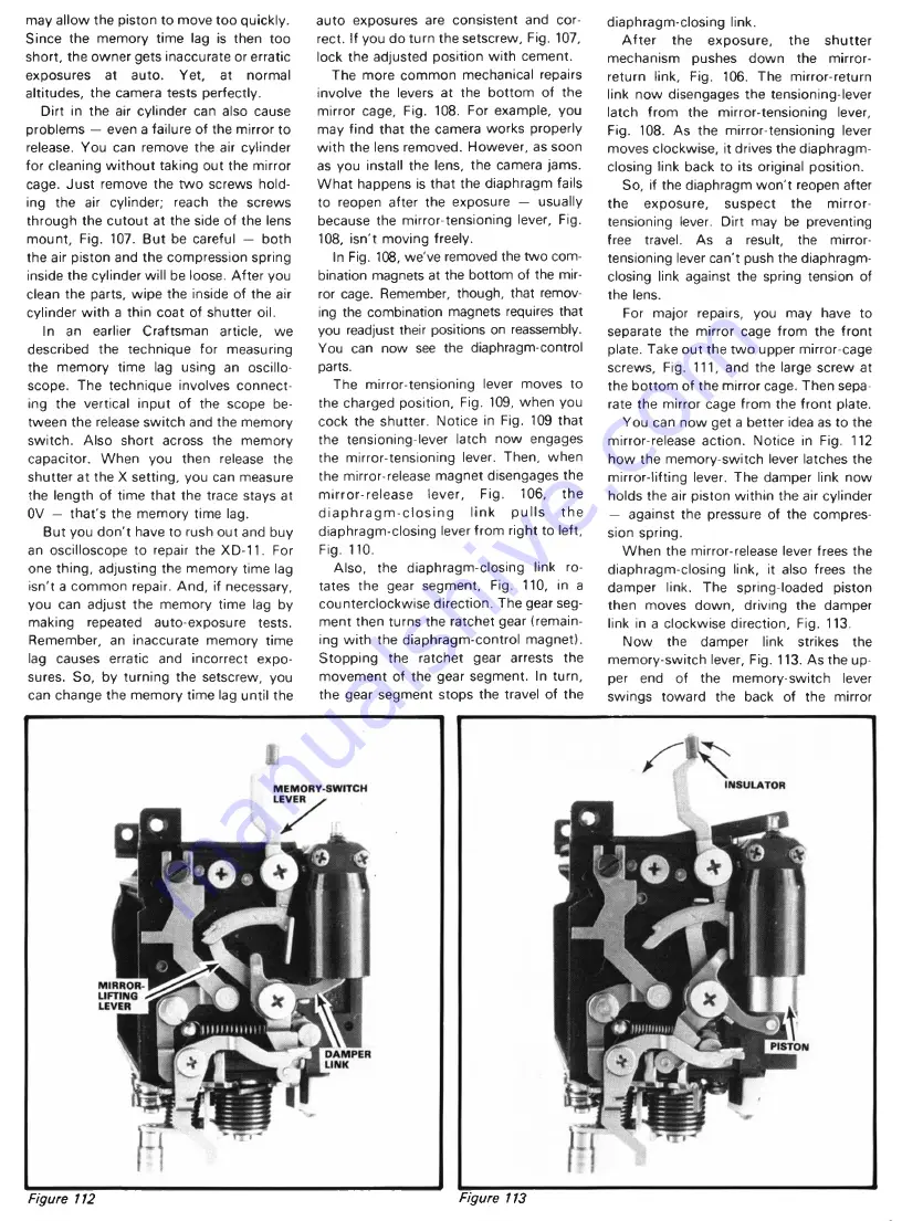
You can now get a better idea as to the
mirror-release action. Notice in Fig. 112
how the memory-switch lever latches the
mirror-lifting lever. The damper link now
holds the air piston w ithin the air cylinder
— against the pressure of the compres
sion spring.
When the mirror-release lever frees the
diaphragm-closing link, it also frees the
damper link. The spring-loaded piston
then moves down, driving the damper
link in a clockwise direction, Fig. 113.
Now the damper link strikes the
memory-switch lever, Fig. 113. As the up
per end of the memory-switch lever
swings toward the back of the mirror
Figure 112
Figure 113


