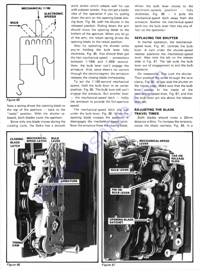
Figure 85
Now a spring drives the opening blade to
the top of the aperture — back to the
"re a d y" position. W ith the shutter re
leased, both blades cover the aperture.
Since only one blade moves during the
cocking cycle, the Seiko has a smooth
wind stroke which adapts well for use
w ith a power winder. You can get a better
idea of the operation if you try pulling
down the arm on the opening-blade driv
ing lever. Fig. 84, w ith the shutter in the
released position. Pulling down the arm
should move the opening blade to the
bottom of the aperture. When you let go
of the arm, the return spring drives the
opening blade to the raised position.
Also try operating the shutter while
you're holding the bulb lever fully
clockwise. Fig. 85. You should then get
the fast mechanical speed — somewhere
between 1/1000 and 1/2000 second.
Here, the bulb lever can't engage the
armature. And, since there's no current
through the electromagnet, the armature
releases the closing blade immediately.
To set the 1/100-second mechanical
speed, hold the bulb lever in its center
position, Fig. 85. The bulb lever still can't
engage the armature. But another lever
— the mechanical-speed latch — holds
the armature to provide the full-aperture
speed.
The mechanical-speed latch sits just
under the bulb lever, Fig. 86. W hen the
opening blade crosses the aperture, it
disengages the mechanical-speed latch.
Now the armature frees the closing blade.
W hen the bulb lever moves to the
electronic-speeds
po sitio n
—
fu lly
clockwise,
Fig. 85 —
it pulls the
mechanical-speed latch away from the
armature. Neither the mechanical-speed
latch nor the bulb lever then has any ef
fect on the operation.
REPLACING THE SHUTTER
In normal operation, the mechanical-
speed lever. Fig. 87, controls the bulb
lever. A cam under the shutter-speed
resistor positions the mechanical-speed
lever. Also note the tab on the release
slide in Fig. 87. The tab pulls the bulb
lever out of engagement to end the bulb
exposure.
On reassembly, first cock the shutter.
Then position the wires through the wire
clamp, Fig. 80, as you seat the shutter on
the mirror cage. Make sure that the bulb
lever
passes to the inside of the
mechanical-speed lever, Fig. 87, and that
the bulb-lever pin sits above the release-
slide tab.
ADJUSTING THE BLADE-
TRAVEL TIMES
Both blades should cross a 20mm
distance in 6ms. To increase the tensions,
rotate the blade ratchets, Fig. 84, in a
Figure 86
Figure 87


