SMART IP ACCESS
7
6.2 Rack mounting the IP Access
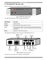
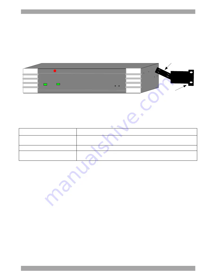
Rack mount the Smart IP Access using the supplied Rack-mount kit. There are 2
possible positions on the side of the Smart IP Access to connect the bracket. Screw
the bracket to the Smart IP Access using 2 screws. See Figure 3. Screw the other
bracket section to the rack.
MINIC
O
M
SMART
IP
ACCESS
Power
Remote
Reset
Local
Screw this section
to side of Smart IP
Access
Screw this section
to the rack
Figure 3 Rack mounting the Smart IP Access
7. Terminology
Below are some terms and their meanings used in this guide.
Term
Meaning
Target Server
The computers/servers that are accessed remotely via the Smart IP
Access.
Client computer
The PC running a remote Smart IP Access session
Remote Session
The process of accessing and controlling Target Servers connected
to Smart IP Access from a User station
8. Client computer operating system
Windows NT4.0, 2000, XP or 2003 Server, with IE 6.0 or higher. 128 bit
encryption is required if a secured connection is selected.
9. Connecting the system
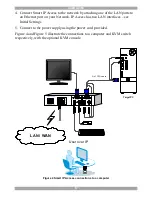
Connect the Target Server / KVM switch to the Smart IP Access as follows:
1. Connect one end of the 3 in 1 CPU cable to the
Computer
ports of the Smart IP
Access.
2. Connect the other end of the 3 in 1 CPU cable to the KVM ports of the Target
Server / KVM switch.
3. To operate the KVM switches and Servers locally, connect a keyboard, mouse
and monitor to the IP Access’s Local Console connectors.

