


SMART IP ACCESS
5
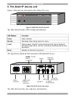
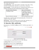
5. The Smart IP Access unit
Figure 1 illustrates the front panel of the Smart IP Access.
MINIC
O
M
SMART
IP
ACCESS
Power
Remote
Reset
Local
Figure 1 Smart IP Access front panel
The table below lists the LEDs, buttons and functions.
LED/Button
Function
Power
Power Indicator
Remote
Illuminates when remote session is active
Local
When pressed, Smart IP Access disconnects the Client computer’s
link to the Target Server, and the Local Mouse and Keyboard become
operational.
Reset
Restarts the Smart IP Access unit
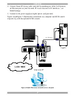
The figure below illustrates the rear panel of the Smart IP Access.
Power
connector
Keyboard
Mouse
Monitor
Computer
Keyboard port
Computer
Mouse port
Computer
Video card
LAN 1
and
2
Ethernet
connectors
SERIAL 1
and
2
RS232
connectors
POWER
100-240 VAC 50/60 Hz
www.minicom.com
CONSOLE
COMPUTER
2
2
1
1
L
A
N
S
E
R
I
A
L
Figure 2 Smart IP Access rear panel
The table below lists the rear connectors and functions.