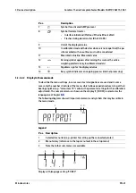

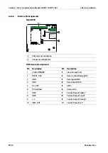
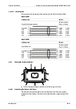
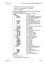
4.2.8.5.3 Cable Diagrams
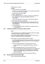
Pin assignments for the cable from the indicator to an RS-232 PC interface (COM1).
Model CAW1P
Indicator side
PC side
25
‑
pin D
‑
Sub male connector
D
‑
Sub connector
9
‑
pin. or 25
‑
pin.
Sgn GND
TxD
RxD
DTR
CTS
1
7
2
3
20
5
5 GND
2 TxD
3 RxD
8 DTR
4 CTS
7 GND
3 TxD
2 RxD
5 DTR
20 CTS
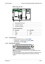
Model CAW1S
Indicator side
PC side
Open cable end
D
‑
Sub connector
9
‑
pin. or 25
‑
pin.
Sgn GND
TxD
RxD
DTR
CTS
15
14
13
12
11
5 GND
2 TxD
3 RxD
8 DTR
4 CTS
7 GND
3 TxD
2 RxD
5 DTR
20 CTS
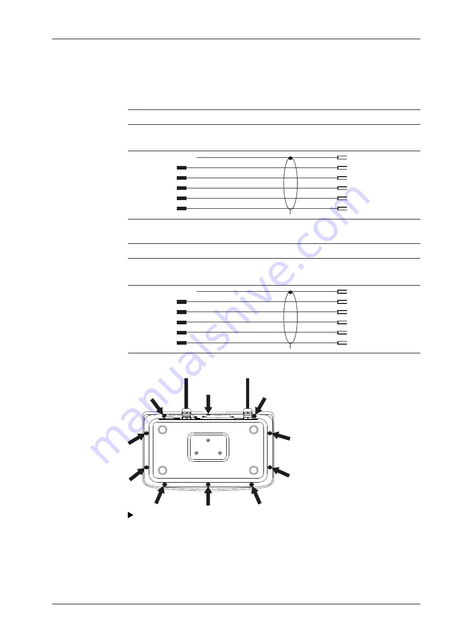
4.2.9
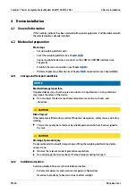
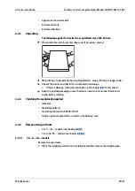
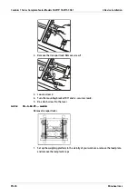
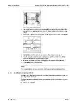
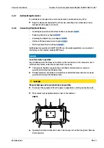
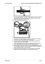
Closing the Combics indicator
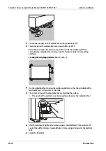
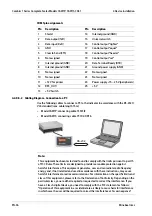
4.2.10 Connecting the Device to AC Power
The indicator is powered through the pre-installed power cord. The power supply is
integrated into the indicator. The device can be operated with a supply voltage of 100 …
240 V.
Put the front panel in place and fasten it with the ten cap nuts (1 Nm).
4 Device installation
Combics 1 Series Complete Scales Models CAW1P, CAW1S, CAS1
Minebea Intec
EN-37
Содержание CAS1
Страница 18: ...CAS1G IG Combics 1 Series Complete Scales Models CAW1P CAW1S CAS1 3 Device description EN 16 Minebea Intec ...
Страница 128: ......
Страница 136: ...Typ Waage Minecomb Typ Auswertegerät TA EG Bauartzulassung T11379 Prüfschein D09 11 02 Typ Minecomb ...
Страница 137: ...Typ Waage Minecomb Typ Auswertegerät TA EG Bauartzulassung T11379 Prüfschein D09 11 02 ...
Страница 138: ...Option Y2 Typ Waage Minecomb Typ Auswertegerät TA EG Bauartzulassung T11379 Prüfschein D09 11 02 ...
Страница 140: ...CAW3S1 60FE NCE Typ Waage Minecomb Typ Auswertegerät TA EG Bauartzulassung T11379 Prüfschein D09 11 02 ...
Страница 141: ......
Страница 142: ......
Страница 143: ...1 5 ...
Страница 150: ......
Страница 151: ......
Страница 152: ......
Страница 153: ......
Страница 154: ......
Страница 155: ......