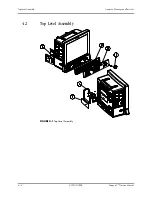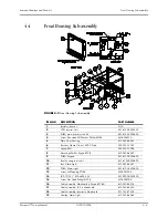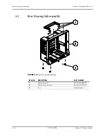
NIBP Module Assembly
Isometric Drawings and Parts List
4 - 12
4.10
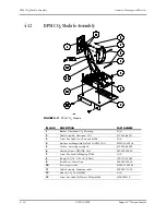
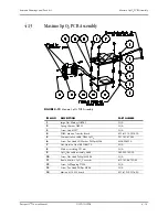
NIBP Module Assembly
FIGURE 4-9
NIBP Module Assembly
ITEM NO
DESCRIPTION
PART NUMBER
1
Plate, NIBP Mounting
N/A
2
PCBA, NIBP PCBA module
801-6100-00019-00
3
Connector. Elbow Reduction, 1/8" & 3/32" ID, White
N/A
4
Connector Tee, 200Barb, 3/32" ID, White Nylon
N/A
5
Tubing. Silicone, 1/16" X 3/16", TYGON 3350 (1feet)
M6G-020006---
6
Air filter hose ID. 1/8", 25um
S1-0378-02-0004
7
Valve, Quick Deflate
801-6101-00012-00
8
Screw, Pan Head Phillips M3X18
N/A
9
Proportional solenoid valve: normally open
801-6101-00013-00
10
Frame, NIBP Tubing Retaining
N/A
11
Tubing, Silicone, Five Branch
N/A
12
Screw, Pan Head Phillips M3X6
N/A
13
TUBE. Silicone, 1/8" X 1/4" X100ft,2800546-100
A21-000002---
14
Pump
801-6101-00014-00
15
Cushion, Pump
6101-20-46761
16
Cable Assembly, NIBP
6100-20-86305
17
Screw, Self-Tapping PT2.6X6
N/A
18
Screw, Flat Head Phillips M2X4
N/A
Содержание Passport V
Страница 1: ...Service Manual ...
Страница 20: ...Main Unit Theory of Operation 1 12 0070 10 0705 Passport V Service Manual This page intentionally left blank ...
Страница 106: ...Services Calibration Procedure 5 10 0070 10 0705 Passport V Service Manual FIGURE 5 9 Calibration ...
Страница 130: ...Printed in U S A 0070 10 0705 Rev A December 3 2009 ...


