MIMAKI JFX-1631/1615 Plus Скачать руководство пользователя страница 32

2-2

How to use the opening/closing door

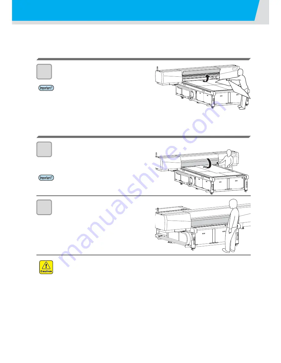
Close the door while performing the drawing to avoid the bad effect to be caused by UV LED.

When setting the media

1

Set the media after opening the door.

When drawing the image

1

Close the door.

2

Perform drawing while keeping the door 
closed.

• When setting the media, avoid contact of the media to the 

door. The door could be closed by vibration.

• Close the door slowly so that the door may not be 

damaged.

• Do not open the door while drawing. The UV light could damage your eyes or skin.
• Inserting your hand while drawing under the door could cause injury due to touching with the carriage.

Содержание JFX-1631/1615 Plus

Страница 1: ...MIMAKI ENGINEERING CO LTD URL http eng mimaki co jp D202017 20...

Страница 2: ...g the USB2 0 interface cable 1 6 Connecting the power cable 1 6 UV LED Unit and Indicator 1 7 UV LED Unit 1 7 Function of indicator 1 7 Setting of ink cartridge 1 8 Kinds of ink that can be used 1 8 A...

Страница 3: ...e print method 3 8 Setting the light intensity of the UV LED 3 10 Setting of priority 3 11 Setting the work change 3 12 Changing language display on the screen 3 13 Output the setting list 3 14 Displa...

Страница 4: ...When the waste ink is pooled up 4 17 Disposing of the ink in the waste ink tank 4 17 Disposing of the ink in the wiper tank 4 18 Regular maintenance for white ink 4 19 Replacing the filter of the cool...

Страница 5: ...image quality declines 5 3 Resolving nozzle clogging 5 3 Stopping the unit during the operation 5 3 Even when ink remains INK NEAR END is displayed 5 4 Troubles for which error messages are given on t...

Страница 6: ...quipment is operated in a commercial environment This equipment generates uses and can radiate radio frequency energy and if not installed and used in accordance with the instruction manual may cause...

Страница 7: ...I and subchapter J indicates compliance with the CDRH regulations and is labeled on the product when marketed in the United States This Model is equivalent to Class II laser device according to CDRH R...

Страница 8: ...and fully understand this Operation Manual before putting the machine into service It is also necessary to keep this Operation Manual on hand Make arrangements to deliver this Operation Manual to the...

Страница 9: ...on of the plotter The symbol indicates helpful information that will facilitate the use of the device Indicates the reference page for related contents The symbol indicates the case where some phenome...

Страница 10: ...ce falls into the category of UN No 3082 and UN Class 9 Since the ink is flammable never use fire when using the device When cleaning the ink station and head be sure to wear the supplied goggle and g...

Страница 11: ...be sure that the device no longer produces smoke and contact a distributor in your district for repair Never repair your device by yourself since it is very dangerous for you to do so Grounding work T...

Страница 12: ...d from burn injury Make sure to replace the lamp after it cools down completely Handling of UV LED Do not use the UV LED in an ambience with a possibility of catching fire gasoline combustible gas spr...

Страница 13: ...e room temperature for three hours or more before using it Open the ink cartridge just before installing it in the printer If it is opened and left for an extended period of time normal printing perfo...

Страница 14: ...d occur may lead to electrical shock of personnel or fire In order to prevent accidents from occurring be sure to carry out periodic inspections and replacement of time change components About firing...

Страница 15: ...place that is not horizontal A place in which temperature and humidity vary by a great margin Use the device under the following environment Operating environment 15 30 C 35 65 Rh A place that vibrat...

Страница 16: ...h the warning label Be sure to fully understand the warning given on the labels In the case where any of the warning label has become so soiled that the warning message is illegible or has come off pu...

Страница 17: ...Position of the warning label Order No Label Order No Label 1 M901549 8 M906311 2 M905980 9 M906318 3 M906115 10 M903764 4 M903330 11 M905624 5 M903226 12 M903239 6 M904325 13 M904121 7 M906310 14 M90...

Страница 18: ...ad This Operation Manual This manual provides the explanation about the displayed characters and used keys on the Display Panel in addition to the operation procedures Proceed operations confirming th...

Страница 19: ...1 4 Carriage 1 5 EMERGENCY SWITCH 1 5 Connecting the cables 1 6 Connecting the USB2 0 interface cable 1 6 Connecting the power cable 1 6 UV LED Unit and Indicator 1 7 UV LED Unit 1 7 Function of indi...

Страница 20: ...kg JFX 1615 JFX 1615plus 4200 mm 2700 mm 1600mm Approx 1300 kg This unit cannot be installed by the customer Its installation should be entrusted to our service personnel or your electrical contracto...

Страница 21: ...4 Operation keys for executing settings required for the machine and a display to display operation items are placed The operation panel is also equipped on the front of this machine Power button This...

Страница 22: ...and so on VACUUM Lamp P 2 5 Lit when media is set BLOW Lamp P 2 11 Lit when media is removed from the table Key P 2 5 Switching VACUUM to BLOW and vice versa VACUUM BLOW key Press to switch over ON O...

Страница 23: ...n the print head cover are mounted on the carriage Depending on UV LED condition the carriage is positioned differently EMERGENCY SWITCH One EMERGENCY switch is placed on the front face of the unit an...

Страница 24: ...2 0 interface is not installed in your computer ask a RIP maker near you or our branch office For supplying power to the device the power distribution board work is required Connecting the power cable...

Страница 25: ...ot expose your naked eyes directly to the light irradiated from the UV LED when it lights Do not touch the lamp when it is being lit or just after it is set OFF It may cause a burn injury as it is ver...

Страница 26: ...k refer to the label attached to the eco cartridge Kind of ink Color LF 200 Ink Magenta Cyan Yellow Black White LH 100 Ink Magenta Cyan Yellow Black White Clear LF 140 ink Magenta Cyan Yellow Black Li...

Страница 27: ...hly Insert the cartridge making the IC chip side facing upward Table of Usable inkset Ink set 1 1 M Magenta C Cyan Y Yellow K Black W White m Light magenta c Light cyan CL Clear P Primer Ink type LF 2...

Страница 28: ...in six months If an extended period of time has passed after opening the cartridge drawing quality would be poor Store ink cartridges in a place that is out of the reach of children When discarding un...

Страница 29: ...al part when placed the drawing surface facing upward The media warping upward could not be absorbed in some cases onto the table Store the media liable to be warped on the slightly smaller platform o...

Страница 30: ...JOG keys 2 Executing Test drawing by pressing the key 3 Executing head cleaning by pressing the key 4 Execute setting of each function by pressing the key Function Mode Press the key during the Local...

Страница 31: ...t drawing 2 7 Execution of test drawing 2 7 Execution of head cleaning 2 8 When cleaning with Normal or Hard or SUBTANK MAINTE 2 8 When cleaning with Wiping 2 9 Cleaning automatically when turning the...

Страница 32: ...image 1 Close the door 2 Perform drawing while keeping the door closed When setting the media avoid contact of the media to the door The door could be closed by vibration Close the door slowly so that...

Страница 33: ...wing 4 Execution of head cleaning 5 Drawing an image from source data 6 Turning the power OFF See Turning the power ON P 2 4 See Setting the media P 2 5 See Test drawing P 2 7 See Execution of head cl...

Страница 34: ...ber Initial operation is started 2 Press the key Local Mode starts 3 Turn the power of connected computer ON When the power is turned ON the Y bar moves To avoid injuries keep your hands away from the...

Страница 35: ...ction the media with the suction vacuum unit option Install the optional suction vacuum unit and then set the media If within the absorption area there are suction holes not closed by the media close...

Страница 36: ...tion area for the media to be set When changing the point of origin please refer to P 3 2 ON OFF 775 mm 1550 mm 2325 mm 3100 mm Origin Seal indicating the point of origin Provided at the 4 corners of...

Страница 37: ...the result is normal finish the operation When the result is abnormal execute head cleaning P 2 8 Printing is disabled when the following messages are displayed It is enabled when the message has disa...

Страница 38: ...completed a mode is returned to the local mode 5 Execute test drawing and check the result of the test drawing Repeat cleaning and test drawing until normal result is obtained normal To be used if te...

Страница 39: ...keys 6 Press the key The cleaning will be started When the cleaning is completed the system is turned to the local mode 7 Execute test drawing and check the result of the test drawing Repeat cleaning...

Страница 40: ...of the head cleaning when turning the power on 1 Select the head with or keys 2 Select execution non execution of the head cleaning with or keys Select execution of cleaning for every head Execute Cle...

Страница 41: ...ing origin is not changed after completion of the drawing If the UV irradiation device is not ready or the temperature of the water heating system has not reached the predetermined value a message is...

Страница 42: ...the drawing stop the drawing operation and erase the received data from the device 1 Press the key while drawing Drawing operation stops When data is transmitted from the computer the computer stops...

Страница 43: ...the drawing If you press key the Y bar will move to the front of the table centering the origin of the drawing 6 Press the key The value is set and the screen returns to Step 2 Evacuation of Y bar fr...

Страница 44: ...off automatically When turning the power OFF Do not turn the main power switch OFF If the main power switch is ON the power periodically turns on and the nozzle drop out prevention function is operate...

Страница 45: ...f priority 3 11 Setting the work change 3 12 Changing language display on the screen 3 13 Output the setting list 3 14 Displaying machine information of this device 3 15 Other useful settings 3 16 Ini...

Страница 46: ...ht pointer mark by pressing the keys Move the light pointer mark to the position to set a new origin 3 Press the key when the drawing origin is determined The origin is changed The setting value for t...

Страница 47: ...rentheses indicates the distance from the origin to the maximum effective area 5 Press the key 6 Select the Y OFFSET by pressing the or keys 7 Press the key 8 Input value by pressing the or keys Setti...

Страница 48: ...the or key 3 Press the key twice 4 Press the or key to enter the thickness of loading media Set value 0 0 to 50 0mm 5 Press the key 6 Press the key to end the setting Adjust head gap with the or keys...

Страница 49: ...area 7 Press the key The media thickness will be measured automatically The measured thickness will be displayed The carriage will move to the evacuation position and the screen returns to the one dis...

Страница 50: ...Input the head gap value by pressing the or key Set value 1 2 to 5 0mm 7 Press the key 8 Press the key several times to end the setting If a correct value is not set to the head gap value the print qu...

Страница 51: ...ight UV LED irradiation time is displayed on the right 3 Press the key to return to the local mode Information on your machine type can be confirmed in P 3 15 Displaying machine information of this de...

Страница 52: ...to be set by pressing the or key As for setting items see the next page 7 Press the key 8 Select a value by pressing the or key As for setting values see the next page 9 Press the key 10 Press the ke...

Страница 53: ...n when the head moves on the media at drawing Higher quality drawing UNI DIR CH2 When drawing is conducted only the right hand side UV LED is used LOGICAL Seek ON The head moves according to the data...

Страница 54: ...setting HIGH The UV LED is lit with 100 of its light intensity STANDARD The UV LED is lit with 75 of its light intensity LOW The UV LED is lit with 50 of its light intensity NONE The UV LED is not li...

Страница 55: ...HOST Setting of the computer has the priority PLOT Setting of this device has the priority 7 Press the key 8 Set other items with the same manner as 6 7 9 Press the key several times to end the setti...

Страница 56: ...ves to the view position set in advance P 2 13 Evacuation of Y bar from the table When the Y bar moving has been completed the machine returns to LOCAL v 7 Press the key When you set this to OFF in th...

Страница 57: ...e local mode 2 Select the DISPLAY by pressing the or key 3 Press the key 4 Select a language by pressing the or key Default is English 5 Press the key 6 Press the key to finish Set value remains after...

Страница 58: ...ode 3 Select the MAINTENANCE by pressing the or key 4 Press the key 5 Select the LIST by pressing the or key 6 Press the key Output of the setting list starts 7 Press the key to finish Set value remai...

Страница 59: ...played by pressing the or key and press the key The following 2 information can be displayed FW version of this device Serial No 7 Press the key several times to end the setting FUNCT I ON V I EW ENT...

Страница 60: ...the number of times for over painting Finer drawing can be obtained by conducting the over painting REFRESH Level 0 to 3 Set the refreshing revel for preventing the head from clogging in a dusty envir...

Страница 61: ...ET by pressing the or key 5 Press the key 6 Press the key Resetting the setup 7 Press the key several times to end the setting In the SETUP RESET resetting is allowed only on contents changed in the S...

Страница 62: ...e media on the correct position using those holes Arrangement of guide holes When you prepare the guide for setting the media please use the following sizes as reference Select a material for the guid...

Страница 63: ...media jam Be careful about it When you use JFX 1631 1615 the Post Cure Unit is an option Be sure to adjust the height of the Post Cure Unit before drawing When the position of the Post Cure Unit is t...

Страница 64: ...y tighten them so that they may not be loosened while drawing 6 Take out the height adjusting jigs Be sure to take them out slowly in order not to damage the media or the suction table surface If used...

Страница 65: ...Cure Unit is an option Compared with JFX 1631 1615 the Y bar cannot move in the gray part of the figure above Set the media on the white part of the figure above You can enlarge the drawing range and...

Страница 66: ...located on the Y bar is turned off 2 Adjust the height of the Post Cure Unit depending on the media P 3 19 3 Attach the UV shade curtain Using the magnets provided with the UV shade curtain attach the...

Страница 67: ...3 23 Use the Post Cure Unit 3 Useful Function Turn on the power supply of the Post Cure Unit 1 Turn on the power supply for the Post Cure Unit located on the Y bar Power supply for the Post Cure Unit...

Страница 68: ...Performs the origin detection operation 7 Press the key several times to end the setting Value Outline Cure Print UV irradiation with the post cure is performed at the same time of drawing In such a c...

Страница 69: ...tes ink REMOTE After REMOTE is set and when first drawing starts the lamp of the post cure unit lights While the machine is in the REMOTE status the lamp lights continuously When you draw multiple dat...

Страница 70: ...When DRAWING RANGE of the maintenance function is after print the right screen is displayed 4 Select ON OFF by pressing the or key and press the key If you select OFF proceed to the Step 8 5 Select th...

Страница 71: ...ter ink curing the Post Cure Unit becomes hot Do not touch it after curing preferably When you set the printing method other than Panel Setting in Print Condition UV mode submenu of RasterLinkPro5 the...

Страница 72: ...after drawing with POST CURE of the setting items P 3 26 Register the number of post cure irradiations and the size length of the image to be drawn with POST CURE after print of the setting items 3 Pe...

Страница 73: ...re is completed the screen on the right is displayed 6 Align the back edge of the image with the post cure irradiation position back edge The back edge of the post cure irradiation position is the pos...

Страница 74: ...st the height there is the danger that the height adjusting jig may damage the drawing surface 2 Set the drawn media on which you re irradiate lamp light on the table End position of lamp light irradi...

Страница 75: ...or key set the number of irradiations Set values 1 to 50 times By the set number of times the Y bar goes and returns with irradiating lamp light 11 Press the key twice Re irradiating UV lamp light sta...

Страница 76: ...fter a while the message on the right will be displayed 4 Press the Y bar to move it to the front Move it until the Y bar cannot move any more 5 Press the key When you use JFX 1631 1615 the Post Cure...

Страница 77: ...st Cure Unit to the top and tighten the screw 8 Remove the lamp side cover L R 9 Remove the socket cover of both sides of the lamp 10 Slide the protection cover Tighten the screw securely If replacing...

Страница 78: ...rotection cover 1 Insert the protection cover in the direction of the arrow in the picture 2 Lift the near side When attaching the lamp be sure to check that electrodes on both edges are surely insert...

Страница 79: ...the right side in order 1 2 3 4 16 Insert the claw at the right edge of the protection cover into the gap of B 17 Slide the protection cover to the left by about 5mm 18 Hook the claw of the left side...

Страница 80: ...over and the lamp side cover and return the Post Cure Unit to the original status 21 Turn on the power supply of the Post Cure Unit and press the key The part shall not come off below the bottom surfa...

Страница 81: ...the periodical wiping ink is not used In addition perform cleaning or replacement of the wiper period ically 3 Raise the refresh level during drawing Chapter 3 Other useful settings of the JFX operati...

Страница 82: ...3 38...

Страница 83: ...e clogging of special color 4 16 When the waste ink is pooled up 4 17 Disposing of the ink in the waste ink tank 4 17 Disposing of the ink in the wiper tank 4 18 Regular maintenance for white ink 4 19...

Страница 84: ...Using white ink Perform sub tank maintenance If unused for about 1 week Remove ink from the ink path If unused for about 2 weeks Clean the ink path Never disassemble the device Disassembling the devic...

Страница 85: ...the end 1 Remove an ink cartridge to be replaced 2 Referring to the label attaching to the cartridge remove the used ink pack 3 Set a new ink pack Referring to the label attaching to inside the cartr...

Страница 86: ...side of the ink pack stopper 2 Move it downward slowly 5 Shut the lid of the cartridge Insert all claws 6 Set a new ink cartridge As shown in the drawing set an ink cartridge turning up a side contain...

Страница 87: ...n the cartridge that is not currently being used Lights in green red in turns Ink remains low in the cartridge that is currently in use Off Ink remains in the cartridge that is not currently being use...

Страница 88: ...els Then shake it more than twenty times right and left so that ink flows inside the cartridge If you shake it too strong the pack inside may be damaged and it may cause ink leakage Therefore perform...

Страница 89: ...all problem cartridges are displayed the menu returns to the LOCAL mode automatically Warnings and operations When the cartridge cannot be switched in one supply system a warning for the supply cartr...

Страница 90: ...lly moves from the standby position to the left front cover on the left 6 Press the key The carriage is lifted down to the cleaning position When the movement is completed you may now move the carriag...

Страница 91: ...g the nozzle surface of the head It would cause the nozzle clogging In case you want to buy special cleaning swab please contact your sales agent or our branch office 9 Press the key after completing...

Страница 92: ...f printing times OFF 1 100 by pressing the or key If it is set to OFF the periodical cleaning is not performed 5 Press the key 6 Select the head and set execution non execution of wiping 1 Select the...

Страница 93: ...printing times OFF 1 100 by pressing the or key If it is set to OFF the periodical cleaning is not performed 7 Press the key 8 Select the head and set execution non execution of cleaning 1 Select the...

Страница 94: ...ey 5 Press the key The carriage automatically moves from the standby position to the left front cover on the left The wiper will move toward you 6 Remove suction nozzle Assy 1 Hold down the rear part...

Страница 95: ...ozzle and clean them if they are dirty 1 Remove hardened ink or the attached dirt using a stick with fine tip 2 Using the dropper drip several drops of cleaning liquid inside the suction nozzle and cl...

Страница 96: ...Assy pressing it firmly under the suction nozzle The wiper M will stick out by around 0 5 mm after being attached 14 When the cleaning is completed press the key The initial movement will be performed...

Страница 97: ...key 2 Select execution of subtank maintenance with key Select the ink filling for all the heads Fill Displays the set ink cartridge Not fill Displays 4 Press the key 5 Press the key Subtank maintenan...

Страница 98: ...ess the key 6 Set the special refresh by pressing the or key 1 Select the head with the key 2 Select execution of special refresh with key Select the ink filling for all the heads Fill Displays the se...

Страница 99: ...waste ink tank 3 When the error disappears remove the waste ink tank 4 Dispose waste ink into the prepared polyethylene tank Before replacing ink put paper on the floor To prevent the floor from being...

Страница 100: ...e the finger screw fixing the wiper tank cover 2 Remove the cover 2 Remove the wiper tank and discard the waste ink Discard the waste ink pursuant to your local regulations 3 Return the wiper tank to...

Страница 101: ...and press the key 3 Select the WHITE MANT with pressing the or key and press the key 4 Select executing white maintenance or not for each head and press the key 1 Select the head with or key 2 Select...

Страница 102: ...e drawing set an ink cartridge turning up a side containing the IC chip 9 Press the key Ink filling starts A message shown in the right is displayed after completion of white ink filling 10 Press the...

Страница 103: ...ews 4 pcs each on the front covers and remove the covers The cooling fans are on the circled places 6 places shown on the below When replacing the cooling fan filter replace all the filters When repla...

Страница 104: ...r screw to remove the filter holder 5 Replace the filter Prepare the new filter and replace with it 6 Return the filter holder to the original state Follow from Step 4 to 6 for all the cooling fans 7...

Страница 105: ...e the cover Remove the screws 4 pcs and open the cover 4 Remove the filter holder Remove the screw and remove the filter holder 5 Replace the filter After replacement attach the filter holder and the...

Страница 106: ...the MAINTENANCE by pressing or key and press the key 3 Select the PRN adjust by pressing or key 4 Press the key twice 3 Select the drawing resolution by pressing or key Setting value 300 600 1200 DPI...

Страница 107: ...is formed at the point 140 10 Adjust it by pressing or key Setting value 0 to 400 When there is no pattern forming a straight line between 0 and 400 1 Once again perform the checking of the head gap P...

Страница 108: ...y 7 Press the key 8 Select the ink filling for each head 1 Move the cursor with or keys 2 Select ink filling with or keys Select ink filling for all the heads Fill The ink cartridge that is set will b...

Страница 109: ...of the ink will start When the ink filling is completed the screen as shown in the right will be displayed If you press the key several times the system will return to the local mode When replacing t...

Страница 110: ...water mixed with antifreeze liquid pursuant to the regulations of your district Be sure to wear goggle and gloves for handling the antifreeze liquid Use the recommended antifreeze liquid by Mimaki An...

Страница 111: ...bottom of this page The antifreeze liquid mixed water inside the piping can also be discharged completely Further this work is performed safely as it may be done after the water heater device has been...

Страница 112: ...ystem and the catch clip to the state of starting the operation 9 Press the key Discharging of antifreeze liquid remaining in the system starts When discharging is completed a message shown in the rig...

Страница 113: ...r heating system cover 3 Set the clip 4 Attach the cover on the left back side of the main unit 14 Press the key 15 Press the key several times to finish Precautions for antifreeze liquid Water and an...

Страница 114: ...nit 3 Remove the catch clips 4 Holing up the water heater device and hang the hanger to the hook 5 Take out the water heater tank Transfer the remaining antifreeze liquid to the separate polyethylene...

Страница 115: ...move the finger screw to remove the filter holder When cleaning be sure to wear the supplied goggles and gloves since you may get ink in your eyes Contact a shop or a sales office when a screw is drop...

Страница 116: ...Replacing the UV LED Unit filter 4 34 5 Replace the film 6 Attach the filter holder 7 Close the right maintenance cover Filter holder Filter...

Страница 117: ...red in this unit 1 Select the UV LED MODE of the maintenance menu 1 Press the key in the local mode 2 Select the MAINTENANCE by pressing the or key and press the key 3 Select the UV LED by pressing th...

Страница 118: ...he key 6 Select resolution by pressing the or keys Setting value 600x300 dpi 600x600 dpi 600x1200 dpi 1200x300 dpi 1200x600 dpi 1200x1200 dpi 7 Press the key 8 Select drawing quality by pressing the o...

Страница 119: ...vel by pressing the or keys Setting value Strong Weak Standard No No Draw Light intensity becomes stronger 3 Press the key 4 Press the key several times to end the setting 5 Check UV curing again Set...

Страница 120: ...mode 2 Select the MAINTENANCE by pressing or key and press the key 3 Select the INVERTER by pressing or key 4 Press the key 2 Press the to set the vacuuming volume Setting value 0 10 3 Press the key 4...

Страница 121: ...rop Pattern by pressing or key 2 Press the key 3 Press the key 4 Press the key The drop pattern drawing starts Check the pattern and determine the optimal drop number for the media you re using When s...

Страница 122: ...4 40...

Страница 123: ...energized 5 2 The device cannot perform printing 5 2 Display WATER NOT READY 5 2 If image quality declines 5 3 Resolving nozzle clogging 5 3 Stopping the unit during the operation 5 3 Even when ink r...

Страница 124: ...been set improperly Display WATER NOT READY When WATER NOT READY appears on the display the water temperature in the water heater has not reached the predetermined value Has the power cable been conne...

Страница 125: ...or stopping the unit urgently for the safety reason One EMERGENCY switch is placed on the front face of the unit and 2 are placed on each of the buck surface and Y bar respectively Development Correct...

Страница 126: ...rtridge enough return the cartridge to the original status Shake the ink cartridge by referring to P 4 6 How to shake an ink cartridge 9 Press the key The cartridge weight currently saved in the ink I...

Страница 127: ...form the procedures from the Step 8 again 12 Register the weight by pressing the key 13 Press the key several times to end the setting You can correct the ink remaining amount value up to 15 times per...

Страница 128: ...e expired Replace an ink cartridge of the displayed head with new one ahead of time P 4 3 Two months and more have passed since ink cartridge expired Replace the ink cartridge of which color is shown...

Страница 129: ...r to the device an turn it on after a while If the same error message appears again on the LCD contact your local distributor to call for service Failed to write onto IC Head setting failure Head data...

Страница 130: ...thin the range of in position even if a certain period of time has been passed Turn off the power to the device an turn it on after a while If the same error message appears again on the LCD contact y...

Страница 131: ...this operation call the dealer or our branch for the service Two months and more have passed since ink cartridge expired Replace the displayed ink cartridge with a new one The ink cartridge is not a M...

Страница 132: ...9 Abnormal water tank temperature Turn off the power to the device an turn it on after a while If the same error message appears again on the LCD contact your local distributor to call for service Wat...

Страница 133: ...he ink set other than the current one The cartridge that matches the ink set is not inserted into the proper position Insert it into the proper position Error message Corrective measure Turn off the m...

Страница 134: ...5 12...

Страница 135: ...Tables of specifications and functions of this unit are described Specifications 6 2 Basic unit specifications 6 2 Specifications for ink 6 3 Function Flowchart 6 5 CHAPTER 6 Appendix...

Страница 136: ...ty 0 2 mm Perpendicularity 0 5 mm 500mm Head gap adjustment Automatic head adjustment enabled Media absorption Adsorptive immobilization by the vacuum unit 1 1 The vacuum unit is an option UV unit UV...

Страница 137: ...LF 140 ink only Primer Primer only Capacity of ink cartridge 600 cc Shelf life One year from the date of manufacture Storage temperature During storage 15 C to 35 C During shipping 0 C to 60 C within...

Страница 138: ...6 4...

Страница 139: ...C YYYYKKKK CL EAN I NG power on Returns to LOCAL when power on is selected DATA CLEAR key LOCA L 2 5mm DATA CL EAR DATA CL EAR ENT LOCA L 2 5mm LOCA L S u b T a n k MMMML L L L L L L LMMMM LOCA L NEGA...

Страница 140: ...V I EW START e n t HEAD HE I GHT MED I A TH I CKNESS e n t HEAD HE I GHT TH I CKNESS CHECK e n t OR I G I N SE L ECT X OF FSET V I EW SET V I EW POS e n t HEAD HE I GHT HEAD GAP e n t FUNCT I ON OR I...

Страница 141: ...GAP P L EASE WA I T V I EW POS I T I ON MM TH I CKNESS CHECK CHECK I NG 1 0 to 5 0 0 to 50 0 9999 to 9999 STANDARD FINE FAST BI D UNI D UNI D CH2 PICTURE MEDIA OFF SET UP PR I NT START e n t SET UP QU...

Страница 142: ...ed To be followed SET UP REFRESH e n t SET UP I NK L AYERS e n t SET UP UV L EVE L e n t SET UP PR I OR I TY e n t SET UP MM I NCH e n t SET UP UV SCAN ADD e n t SET UP SETUP RESET e n t SET UP POST C...

Страница 143: ...0 to LEVEL 3 SET UP DRAWI NG e n t SET UP DRAWI NG L EVE L 1 SET UP I N I T I A L I ZE OK e n t SET UP UV SCAN ADD 0 0 to 9 PRINT REMOTE NONE normal 0 to 60 sec SET UP POST CURE PR I NT P r i n t E n...

Страница 144: ...j u s t e n t MA I NTENANCE F I L L UP I NK e n t MA I NTENANCE I NKSET e n t Followed Followed To be followed To be followed MA I NTENANCE PER I OD I C MA I NTE e n t FUNCT I ON MA I NTENANCE ENT MA...

Страница 145: ...WI P I NG e n t OFF 1 to 100 I NT CL EAN I NG PR I NT COUNT 1 0 I NT CL EAN I NG TYPE n o r ma l PER I OD I C MA I NTE CL EAN I NG e n t I NT CL EAN I NG MMMMCCCC YYYYKKKK I NT WI P I NG MMMMCCCC YYYY...

Страница 146: ...v e l S e t e n t MA I NTENANCE UV L ED e n t MA I NTENANCE SP REFRESH e n t Followed Followed To be followed To be followed MA I NTENANCE SUBTANK MA I NTE e n t MA I NTENANCE WH I TE MANT e n t MA I...

Страница 147: ...t P l a t e YES I n k L e v e l S e t S l o t 3 C WE I GHT 3 2 5 g SPEC I A L REFRESH MMMMCCCC YYYYKKKK L ED T I MER CHANNE L CH1 L ED T I MER I N I T I A L I ZE OK e n t CH1 CH2 CH3 CH4 ALL UV L ED...

Страница 148: ...I NFOMAT I ON e n t MA I NTENANCE I NVERTER e n t MA I NTENANCE D r o p P a t t e r n e n t MA I NTENANCE L I ST e n t MA I NTENANCE REP L ACE P CURE e n t MA I NTENANCE WATER CHNG e n t MA I NTENANCE...

Страница 149: ...10 MOV I NG NOW P L EASE WA I T REP L ASE POST CURE END e n t REP L ASE POST CURE START e n t REP L ASE POST CURE PUSH Y BAR FRONT e n t SEARCH I NG OR I G I N P L EASE WA I T REP L ASE POST CURE P CU...

Страница 150: ...6 16 Followed FUNCT I ON D I SP L AY ENT D I SP L AY E n g l i s h e n t Japanese English FUNCT I ON POST CURE ENT POST CURE START POS 0mm 0 to 3100mm...

Страница 151: ...Function Flowchart 6 17 6 Appendix POST CURE COUNT 2 POST CURE END POS 0mm POST CURE P L EASE WA I T POST CURE START e n t 0 to 3100mm 1 to 50...

Страница 152: ...6 18...

Страница 153: ...D202017 20 25122014...

Страница 154: ...SN FW 2 80 MIMAKI ENGINEERING CO LTD 2014...

Отзывы: