19
WARNING
ALWAYS DISC ONNECT ELECTRICAL
POWER FROM THE PUMP MOTOR AND
ECC B EFORE PE RFORMING A NY
MAINTENANCE. FAILURE TO FOLLOW
THESE INSTR
UCTIONS COULD
RESULT IN DEATH OR SER
IOUS
INJURY.
2. Disconnect power from ECC.
3. Remove PCB (Paragraph 4.4.1).
4. Remove fee dback potentiometer ( Paragraph
4.5.1).
5. Remove screw that se cures c apacitor (6 5) (i f
installed) to ECC . Slid e ca pacitor to on e s ide
away from nylon worm gear (190). Leave wires
attached.
6. Using a 3/32 punch, push out spring pin hold-
ing nylon gear on shaft. Remove gear.
4.6.2 Installation of Nylon Worm Gear
1. Slide ne w n ylon wor m ge ar (1 90) over moto r
shaft and align shaft holes to gear holes with 3/
32 punch. Being careful not to da mage nylon
worm ge ar, pr ess sp ring pin (2 00) thr ough
holes in gea r a nd shaft. Pla ce pin eq ual d is-
tance from both sides of gear.
2. Reinstall c apacitor (6 5) ( if r emoved). T ighten
screw. Do not allow wires to be pinched under
capacitor.
3. Install feedback potentiometer (Paragraph
4.5.2).
4. Install PCB (Paragraph 4.4.2).
5. Perform calibration A.
4.7 MOTOR REPLACEMENT
4.7.1 Removal of Motor
1. Apply power and set pump stroke adjust knob
to 0% settin g or remove power and manually
turn the pump stroke adjust knob to 0% setting.
WARNING
ALWAYS DIS CONNECT ELECTRICAL
POWER FROM THE PUMP MOTOR AND
ECC BEFO RE PER FORMING AN Y
MAINTENANCE. FAILURE TO FOL LOW
THESE INSTR
UCTIONS COULD
RESULT IN DEATH
OR SE RIOUS
INJURY.
2. Disconnect power from ECC.
3. Disconnect ECC fro m pum p. Remove four
bolts/screws that mo unt ECC to br acket an d
carefully remove ECC from pump.
4. Disconnect gea r bo x (mRo y A and B has no
gear box) from ECC. Remove four screws that
mount gear box to ECC a nd carefully remove
gear box from ECC.
5. Clean grease from gea r located at bottom of
motor sha ft. Using a 1 /8 pu nch p ush o ut
spring pin holding gear and slide gear off shaft.
Retain gear and spring pin. Parts will be used
during installation of new motor.
6. On mRoy A and B ECCs use a 3/16 punch and
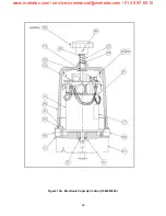
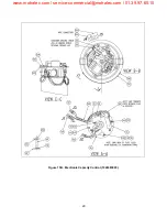
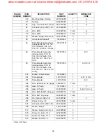
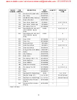
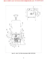
push o ut spr ing pin ( Figure 16 a nd 17, item
920) ho lding dr ive shaf t ( 910). Remo ve dr ive
shaft. Retain drive shaft and spring pin. Parts
will be used during installation of new motor.
7. Remove PCB (Paragraph 4.4.1, Steps 4-6).
8. Lossen two screws for feedback potentiometer
and slide potentiometer away from worm gear.
9. Note p lacement o f wir ing to J1 for ide ntical
placement during inst allation of new moto r.
Remove two cable ties fro m connector J1 wir-
ing.
10. Carefully remove two screws (Figure 15, item
140) from ad apter plate ( 60) and remove
adapter plate from motor.
11. Remove motor wires from J1.
12. Remove four mounting screws (50) from bot-
tom of base (10) and remove motor.
www.motralec.com / [email protected] / 01.39.97.65.10
Содержание MacRoy
Страница 19: ...11 Figure 7 Conversion Detail www motralec com service commercial motralec com 01 39 97 65 10...
Страница 20: ...12 THIS PAGE INTRNTIONALLY BLANK www motralec com service commercial motralec com 01 39 97 65 10...
Страница 24: ...16 Figure 12 Circuit Board Bottom www motralec com service commercial motralec com 01 39 97 65 10...
Страница 38: ...30 THIS PAGE INTENTIONALLY BLANK www motralec com service commercial motralec com 01 39 97 65 10...
Страница 54: ...46 THIS PAGE INTENTIONALLY BLANK www motralec com service commercial motralec com 01 39 97 65 10...
Страница 61: ...53 THIS PAGE INTENTIONALLY BLANK www motralec com service commercial motralec com 01 39 97 65 10...
Страница 63: ...55 THIS PAGE INTENTIONALLY BLANK www motralec com service commercial motralec com 01 39 97 65 10...


