background image

28

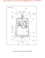
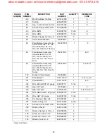
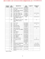
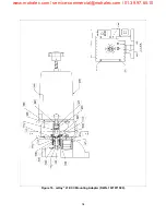
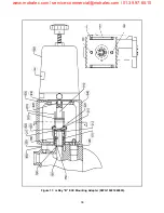
Figure 15A.  Electronic Capacity Control (1022483000).

www.motralec.com / [email protected] / 01.39.97.65.10

Содержание MacRoy

Страница 1: ...________ Installation Location ________________________________ Electronic Capacity Control maxRoy B MacRoy mRoy and Milroyal Product Family Pumps 339 0083 000 ISSUED 01 2012 This manual supersedes th...

Страница 2: ...ents of your pump are recommended for the solution chemical to be pumped Pumps Water Primed All pumps are tested with water at the factory If your process solution is not compatible with water flush t...

Страница 3: ...n working on or near chemical metering pumps Follow directions and warnings provided with the chemicals from the chemical manufacturer User is responsible for determining the hazards associated with t...

Страница 4: ...t to the required voltage 115 or 230 VAC DIP switches are set for desired operation Command input signal is set to desired operation 4 20 mA or 1 5 VDC Factory set at 4 20 mA Feedback signal output is...

Страница 5: ...of 0 to 100 CALIBRATE If actuator was installed on the pump at the factory it has been factory calibrated If actuator is a retrofit or a non standard range is desired follow the calibration instructi...

Страница 6: ...Kit Is Replaced5 2 2 UNPACKING 5 2 3 STORAGE IDLE SERVICE 6 2 4 SAFETY PRECAUTIONS 6 2 5 MOUNTING 6 2 6 ELECTRICAL CONNECTIONS 6 2 6 1 Installation of Input Output Command Signal Wiring 7 2 6 2 Input...

Страница 7: ...tallation of Feedback Potentiometer 18 4 6 NYLON WORM GEAR REPLACEMENT 18 4 6 1 Removal of Nylon Worm Gear 18 4 6 2 Installation of Nylon Worm Gear 19 4 7 MOTOR REPLACEMENT 19 4 7 1 Removal of Motor 1...

Страница 8: ...RE 8 Jumper Plugs Action Mode Conversion 13 FIGURE 9 Effect of Zero Span Controls 14 FIGURE 10 Split Range Operation w Two Pumps Typical pH Control System 14 FIGURE 11 Circuit Board Top 15 FIGURE 12 C...

Страница 9: ...CC to the required position As the ECC moves it changes th e position of the pu mp s str oke ad just shaft thus altering the pump s flow rate Refer to Table 1 wh ich list s r eference ma nuals contain...

Страница 10: ...und on the pump data plate mounted to the pump There are four ECC s customarily supplied with a pump th ese models are sh own in th e product model code tables Table 2 T able 8 There are several very...

Страница 11: ...sion Proof FM Approved 115 VAC 50 60 Hz PPGX682LMH Explosion Proof FM Approved 230 VAC 60 Hz PPGX782LMH Explosion Proof FM Approved 230 VAC 50 Hz Table 6 Milroyal D Model Codes MODEL NUMBER ENCLOSURE...

Страница 12: ...EN61010 EMC EN50081 and EN50082 CENELEC EN50014 and EN50018 Declarer s Name Address Milton Roy Company Flow Control Division 201 Ivyland Road Ivyland PA 18974 USA Type of Equipment Industrial Actuato...

Страница 13: ...ofit Kit Is Replaced After a conversion kit is installed in the field and or a new ECC circuit board ECC s built after Janu ary 2000 fails order replacement board p n 30300 for all pu mps except Milro...

Страница 14: ...tools protective clothing and eye protection when wor king on the e quipment and inst all th e equipment with a view toward ensuring safe opera tion Follow the instructions in this manual and take add...

Страница 15: ...be either 4 20 mA or 1 5 VDC A five position Dip switch SW2 F igure 11 located on the top of th e circuit board selects the control signal used by the operator The f actory se ts SW2 fo r the model o...

Страница 16: ...ET TO THE VOLT AGE LISTED ON YOUR DATA PLATE FIGURE 1 OR 2 OR DAMAGE TO MOTOR WILL RESULT Voltage s elector switch SW1 Figure 11 locate d on top of the circuit board is a two position switch used to c...

Страница 17: ...ON YOUR DATA PLATE FIGURE 1 OR 2 OR DAMAGE TO MOTOR WILL RESULT 5 Voltage sele ctor switch SW1 Figure 11 located o n top of the ci rcuit bo ard is a two position switch used to co nfigure the ECC for...

Страница 18: ...10 Figure 5 Circuit Board 30033 Figure 6 Circuit Board 0152226XXX 0152195XXX www motralec com service commercial motralec com 01 39 97 65 10...

Страница 19: ...11 Figure 7 Conversion Detail www motralec com service commercial motralec com 01 39 97 65 10...

Страница 20: ...12 THIS PAGE INTRNTIONALLY BLANK www motralec com service commercial motralec com 01 39 97 65 10...

Страница 21: ...ed See ECC Calibration Section 4 3 2 1 Operating Modes The Milton Roy ECC can be se t for on e of two modes of operation The operating mode must be established before the control signal can be set up...

Страница 22: ...hat range Adjusting the span control VR1 Figure 11 determines th e m aximum tr avel o f t he ECC over the full r ange o f the com mand signal Adjusting the zero control VR2 Figure 11 shifts the positi...

Страница 23: ...mA operating range this signal will be 4 mA f or a 1 2 20 m A ra nge th e lo wer sig nal will be 12 mA 5 Turn the Ze ro VR2 adjust control until the pump cap acity ind icator rin g move s to the desir...

Страница 24: ...16 Figure 12 Circuit Board Bottom www motralec com service commercial motralec com 01 39 97 65 10...

Страница 25: ...ial Sa fety Dat a Sheet M SDS A completed MSDS must b e packed in th e shipping crate if the ECC is returned attached to a pump These safety precau tions will aid the troubleshooting and repair proced...

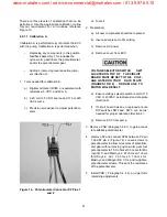
Страница 26: ...T IN DEATH OR SE RIOUS INJURY 2 Disconnect electrical power to ECC 3 Remove PCB Paragraph 4 4 1 4 Remove two screws that secure potentiometer bracket gear asse mbly Re move feed back potentiometer 4 5...

Страница 27: ...OWER FROM THE PUMP MOTOR AND ECC BEFO RE PER FORMING AN Y MAINTENANCE FAILURE TO FOL LOW THESE INSTR UCTIONS COULD RESULT IN DEATH OR SE RIOUS INJURY 2 Disconnect power from ECC 3 Disconnect ECC fro m...

Страница 28: ...n equal distance from both sides of gear 12 Apply lithium grease to gear above and mount gear box to ECC with four screws mRoy A and B has no gear box 13 Mount ECC to pump Connect ECC to pump bracket...

Страница 29: ...e AC power d Remove cover from ECC VOLTAGE SELECTOR SWITCH SW1 LOCATED ON TOP OF THE CIRCUIT BOARD MUST BE SET TO THE VOLT AGE LISTED ON YOUR DATA PLATE FIGURES 1 OR 2 OR DAM AGE TO MOTOR WILL RESULT...

Страница 30: ...B Milr oyal B C G MacRoy G and D uses a 20 1 gearbox It re quires 200 turns at the a ctuator ha ndwheel to adjust the pump str oke 10 tu rns 0 to 100 The Milroyal D uses a 5 1 or 12 1 13 Manually tur...

Страница 31: ...isconnect motor lead J1 Apply a 4 mA 1 VDC signal and adjust zero pot VR2 until both motion lights are off CR5 and C R6 Adjust lower limit LED CR3 until just on VR3 if needed Adjust feedback zero pot...

Страница 32: ...nufacturer on circuit card 30300 39320 when the series pump it is being used on is specified NOTE Values above must be obtained with feed back potent iometer connector J2 unplugged Replace J2 after re...

Страница 33: ...ct acting or 100 for reverse act ing 8 Install ECC to pump Do not rotate ECC shaft If necessary slightly r otate pump coupling for proper engagement with ECC drive pin Install and tighten mounting bol...

Страница 34: ...replace plugs and or wiring as necessary Bad printed circuit board Replace PC board ECC does not respond to 4 20 mA command signal No power to ECC Correct by applying AC power to ECC Polarity of 4 20...

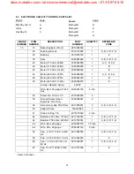
Страница 35: ...d item numbers 2 Description Column a The name of the item is in the description column 3 Part Number Column a The supplier s part number is listed in th e part number column 4 Quantity Column a The n...

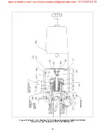
Страница 36: ...28 Figure 15A Electronic Capacity Control 1022483000 www motralec com service commercial motralec com 01 39 97 65 10...

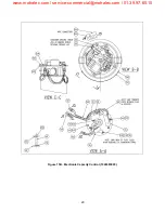
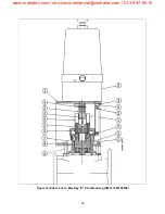
Страница 37: ...29 Figure 15B Electronic Capacity Control 1022483000 www motralec com service commercial motralec com 01 39 97 65 10...

Страница 38: ...30 THIS PAGE INTENTIONALLY BLANK www motralec com service commercial motralec com 01 39 97 65 10...

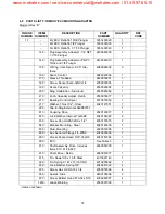
Страница 39: ...20 VAC P 400 2280039010 1 E Jumper Reverse Acting 40229 1 Wire BLU 22 gauge P 400 only 4060387150 4 inch 50 Screw No 10 32 x 1 2 4050005063 4 55 Ground Screw Green Explosion Proof Only 4050306021 2 56...

Страница 40: ...t 10 Turns 152070103 1 A D E G 100 Bracket Potentiometer 152068062 1 101 Potentiometer 4911121010 1 A D E F G 101 Potentiometer 4911121002 1 B C 102 Wire BLK WHT 22 gauge 4060387111 7 inch 103 Gear 18...

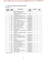
Страница 41: ...059014 1 E 310 O ring 0 239 x 0 070 BUNA 4080109071 1 320 Spring 4030125042 1 340 Clip Retaining 4040107135 1 350 Knob Hand 2550039000 1 360 Pin Spring 0 125 x 1 1 4 4010003132 1 370 Label Explosion 2...

Страница 42: ...34 Figure 16 mRoy A ECC Mounting Adapter DWG 1021971000 www motralec com service commercial motralec com 01 39 97 65 10...

Страница 43: ...l 2370076052 1 217 Washer Thrust 5 16 Steel 4040147031 1 810 Coupling Drive 2520138077 1 820 Lockwasher Drive Coupling 6 Inter nal Tooth 4040104071 2 830 Screw Drive Coupling Pan Head 6 32 x 3 8 40501...

Страница 44: ...36 Figure 17 mRoy B ECC Mounting Adapter DWG 10221460003 www motralec com service commercial motralec com 01 39 97 65 10...

Страница 45: ...aring Control Spool 2370075052 1 217 Washer Thrust 1 2 Steel 4040147051 1 220 Clip E Ring External 4049983151 1 810 Coupling Drive 2520120077 1 820 Lock Washer Internal Tooth 8 4040104082 2 830 Screw...

Страница 46: ...38 Figure 18 Sheet 1 of 2 MacRoy G ECC Mounting Adapter DWG 1022118000 Design through September 2004 and Milroyal G www motralec com service commercial motralec com 01 39 97 65 10...

Страница 47: ...39 Figure 18 Sheet 2 of 2 MacRoy D ECC Mounting DWG 1022728000 www motralec com service commercial motralec com 01 39 97 65 10...

Страница 48: ...Shaft See Note 60284 1 A B 175 Scale Stroke 2530046062 1 A B 181 Insert Stroke Screw See Note 60285 1 A B 190 O Ring Parker 2 246 Buna N 4080095371 1 A B 200 Cover 60986 1 A B 200 Cover 61255 1 C 201...

Страница 49: ...et Mounting 61245 1 C 517 Guard Side 2490108006 1 A B 517 Guard Modified 61244 1 C 519 Guard Modified Side Slotted 60292 1 A B 520 Screw 4050282087 4 A B 520 Screw Btn Hd Soc 10 32X3 8 4050282027 2 C...

Страница 50: ...42 Figure 19 maxRoy B ECC Mounting Adapter DWG 1021572000 www motralec com service commercial motralec com 01 39 97 65 10...

Страница 51: ...56 x 7 16 4010004012 1 O ring 2 223 Buna N 4080095141 1 Knob Stroke Indicator 60550026077 1 Drum Control 60550047074 1 Ring MAXROY B 64400002021 2 Lubricant O ring 4070311000 1 830 Lockwasher Metric f...

Страница 52: ...44 Figure 20 Sheet 1 of 2 Milroyal B ECC Mounting Adapter DWG 1022095000 www motralec com service commercial motralec com 01 39 97 65 10...

Страница 53: ...45 Figure 20 Sheet 2 of 2 Milroyal B ECC Mounting Adapter Guard Assembly DWG 1022095000 www motralec com service commercial motralec com 01 39 97 65 10...

Страница 54: ...46 THIS PAGE INTENTIONALLY BLANK www motralec com service commercial motralec com 01 39 97 65 10...

Страница 55: ...Lockwasher 3 8 Medium C S 4040041022 7 352 Nut 3 8 16 NC S S 4050066012 3 360 Indicator Ring 2190088062 1 370 Indicator Knob 2550037014 1 380 Coupling 2520121006 1 390 Bearing Pin 2110056052 2 410 Dri...

Страница 56: ...48 Figure 21 Milroyal C ECC Mounting Adapter DWG 10222850002 www motralec com service commercial motralec com 01 39 97 65 10...

Страница 57: ...3 611 Adapter 2720116062 1 615 Flatwasher 3 8 4040009012 3 621 Lockwasher 3 8 4040041022 3 625 Hex Nut 3 8 4050066012 3 631 Spline Shaft 2520147006 1 Gear Parts Includes The Fol lowing Parts Items 63...

Страница 58: ...dicator Tube Part of P N 39647 2450029062 1 694 Set Screw 5 16 18 x 5 16 Lg 4050044025 2 695 Gearbox without ECC L ead Screw 2280038000 1 696 Hex Hd Cap Screw 3 8 16 x 1 Lg 4050018119 2 Grease 407 030...

Страница 59: ...51 Figure 22 Milroyal D ECC Mounting Adapter DWG 1022906000 www motralec com service commercial motralec com 01 39 97 65 10...

Страница 60: ...pring 4040039022 4 352 Nut Hex 1 4 20NC 4050064012 4 360 Ring Calibration Aluminum 2530025062 1 405 Stud Mounting 2320034006 4 410 Shaft Drive 2680063062 1 413 Pin Spring 0 187 x 13 x 16 4010005062 1...

Страница 61: ...53 THIS PAGE INTENTIONALLY BLANK www motralec com service commercial motralec com 01 39 97 65 10...

Страница 62: ...he cou pling slot IMPROPER CONNECTION OF THE POWER LINE OR INCORR ECT SUPPLY VOLTAGE CAN CAUSE DAMAGE TO THE EC C D ISCONNECT ALL POW ER BEFORE CONNECTING WIRES 6 Connect electrical connections Paragr...

Страница 63: ...55 THIS PAGE INTENTIONALLY BLANK www motralec com service commercial motralec com 01 39 97 65 10...

Страница 64: ...281 A loosen the two set scr ews 4 05 AL and slide aside the two lead screw keys 211 A This will free up the lead screw 256 A 4 Rotate the micrometer knob turning it counter clockwise Remo ve th e en...

Страница 65: ...o tha t the do wel pin 4 30 can be installed 13 Install the dowel pin and tap flush 14 Locate th e be aring pin 390 and pu t an E Ring on one end Slide the bearing pin on until it bottoms against the...

Страница 66: ...two keys 290 aside This will free the lead screw shaft 102 for removal 6 Unscrew the handknob The entire lead screw shaft will come out the rear of the pump 7 Using p ocket kn ife an d plie rs re move...

Отзывы: