background image

 Troubleshooting

4-3

DVC4000

 Operator’s Guide/Tech Ref Manual

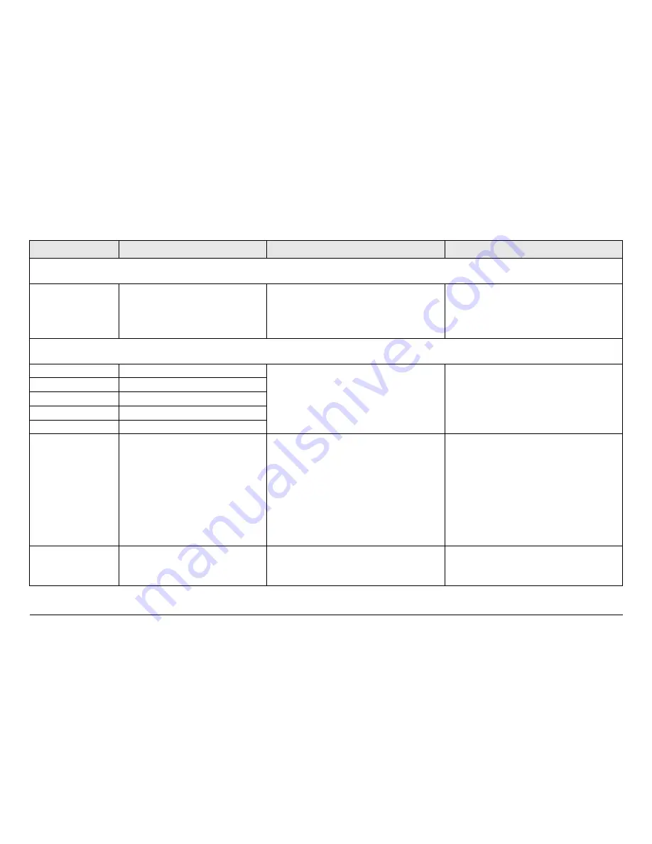
Table 4-2: DVC4000-E Encoder Primary Error Codes 

Error Code

Meaning

Suggested Operator Action

Suggested Technical Staff Action

Status Errors

(Some part of System is reporting an abnormal condition.)

E080

C106 Comm Error Fault

Verify condition of cable connections.

Verify operation of ancillary 
equipment.

Contact technical staff.

If problem persists, possible hardware 
failure.  Contact MRC Technical Support.

Parameter Errors

(Some internal parameter is outside of allowable limits.)

E330

DCC 5.5 Volt Line Fault

Contact technical staff.

If problem persists, possible hardware 
failure.  Contact MRC Technical Support.

E331

DCC 5 Volt Line Fault

E332

DCC +12 Volt Line Fault

E333

DCC -12 Volt Line Fault

E334

DCC Ref DCC Volt Fault

E335

DCC Temperature Fault

Verify DVC4000-E internal fans are 
operating.

Check DVC4000-E to be certain it is 
not too close to sources of heat.  
Relocate unit, if possible.

Verify DVC4000-E has room around it 
for proper air flow.  Move objects 
preventing proper air flow.

Contact technical staff.

If problem persists, possible hardware 
failure.  Contact MRC Technical Support.

E336

DCC Fan Current Fault

Confirm all DVC4000-E internal fans 
are operating.

Contact technical staff.

If problem persists, possible hardware 
failure.  Contact MRC Technical Support.

Содержание DVC 4000

Страница 1: ...DVC4000 Digital Video Encoder and Digital Video Decoder Operator s Guide Manual Part No 400516 1 Rev B December 2008 ...

Страница 2: ......

Страница 3: ... 978 671 5700 Printed in U S A Adobe the Adobe logo Acrobat and Reader are registered trademarks of Adobe Systems Inc in the United States and or other countries Proprietary Material The information and design contained within this manual was originated by and is the property of Microwave Radio Communications Microwave Radio Communications reserves all patent proprietary design manufacturing repro...

Страница 4: ...nt WEEE For more information about where you can drop off your waste equipment for recycling please contact your local government office Except for this notification and the proper marking of products with the appropriate symbol Microwave Radio Communications disclaims responsibility for the disposal of its products per the WEEE directive Symbols Used The following symbols are used on the equipmen...

Страница 5: ...des all costs of shipping customs clearance and other related charges If MRC determines that the product is not defective within the terms of this warranty Buyer will pay MRC all costs of handling transportation and repairs at the then prevailing repair rates d All the above warranties are contingent upon proper use of the product These warranties will not apply 1 if adjustment repair or product o...

Страница 6: ...IES STATED HEREIN MRC DISCLAIMS ALL WARRANTIES ON PRODUCTS FURNISHED HEREUNDER INCLUDING WITHOUT LIMITATION ALL IMPLIED WARRANTIES OF MERCHANTABILITY AND FITNESS FOR A PARTICULAR PURPOSE MRC WILL HAVE NO RESPONSIBILITY FOR ANY PARTICULAR APPLICATION MADE OF ANY EQUIPMENT Any description of equipment whether in writing or made orally by MRC or its agents specification sheets models bulletins drawin...

Страница 7: ...nt Options 2 3 System Integration 2 3 DVC4000 Configurations 2 3 DVC4000 E Digital Video Encoder 2 4 DVC4000 D Digital Video Decoder 2 4 For More Information 2 5 Routine Operation 3 1 Chapter Overview 3 1 Overview of Controls Indicators and Connectors 3 1 DVC4000 Controls and Indicators 3 1 DVC4000 E Encoder Connectors 3 2 DVC4000 D Decoder Connectors 3 4 Preparing for Operation 3 5 Fixed or Mobil...

Страница 8: ... NTSC Pedestal Settings 3 54 Monitor Change Audio Output Settings 3 55 Monitor Audio A Status 3 56 Monitor Change Audio A Attenuation Level 3 58 Monitor Audio A Rate 3 59 Monitor Audio B Status 3 61 Monitor Change Audio B Attenuation Level 3 62 Monitor Audio B Rate 3 64 Monitor Change Video Loss Settings 3 65 Monitor Change Gen Lock Settings 3 66 Monitor Change Gen Lock Offset Settings 3 68 Monito...

Страница 9: ...re Version 5 0 and later Click on the following icon to download your FREE copy of the latest Adobe Reader software When viewing this manual on line text displayed as blue contains a hypertext link Click on the blue hypertext link to jump to that destination If the destination link is also blue click on the blue destination link to return 1 3 What This Manual Covers This manual describes how to op...

Страница 10: ...nnel Users of this manual should already be familiar with basic concepts of radio video and audio 1 6 Related Documents DVC4000 Digital Video Encoder and Digital Video Decoder Technical Reference Manual part no 400517 1 DVC4000 Digital Video Encoder and Digital Video Decoder Quick Reference Card part no 400518 1 1 7 Ordering Documentation Any of the above manuals may be ordered by contacting MRC C...

Страница 11: ... Support please have the following information available Model number and serial number of the unit This is located on a label on the bottom of each unit Approximate purchase date Firmware revision which appears on the DVC4000 alphanumeric display System Menu System Info menu 1 9 Supported Repairs The DVC4000 Digital Video Encoder and the Digital Video Decoder were designed to be compact rugged an...

Страница 12: ...Guide Or you can E mail our Technical Support team at support mrcbroadcast com Be sure to tell us what product you re writing about and which manual the Operator s Guide the Quick Reference Card or the Technical Reference Manual Feedback ...

Страница 13: ...al Video Decoder 2 4 For More Information 2 5 Figure 2 1 DVC4000 Used for transmitting and or receiving digital signals and compressed video signals through microwave radio communications links the DVC4000 provides maximum flexibility to support multiple configuration requirements with user friendly Preset selections The DVC4000 is ideal for Electronic News Gathering ENG and Digital Video Broadcas...

Страница 14: ...ions of the DVC4000 are identified and described in the Routine Operation Chapter on page 3 1 Digital Video Encoder Configuration The DVC4000 E configuration contains a BNC analog VIDEO input connector DB 9 analog AUDIO A and AUDIO B input connectors a BNC SDI input connector and a BNC ASI OUT output connector See Figure 2 3 Digital Video Decoder Configuration The DVC4000 D configuration contains ...

Страница 15: ...nal information 2 2 4 Mounting and Deployment Options The DVC4000 may be used in either fixed or mobile applications For fixed or mobile application installations the DVC4000 is usually mounted in a standard 19 inch 48 3 cm rack For more details on installation of the DVC4000 in various applications see the Installation Chapter on page 5 1 part of the DVC4000 Technical Reference Manual only 2 2 5 ...

Страница 16: ...tal AUDIO IN IMB POWER Analog VIDEO IN VIDEO TS ASI OUT SDI IN ASI OUT MICROPROCESSOR RS232 SUM ALARM Optional 2 3 2 DVC4000 D Digital Video Decoder The DVC4000 D block diagram is shown in Figure 2 6 Figure 2 6 DVC4000 D Digital Video Decoder POWER SUPPLY AC DC POWER DISTRIBUTION COMMAND AND CONTROL AND FRONT PANEL DISPLAY KEYPAD CONTROL DECODER STATUS MPEG DECODER Analog Digital AUDIO A OUT Analo...

Страница 17: ...n the DVC4000 Technical Reference Manual only Specific topics contained in the Technical Reference Manual are listed below Topic Chapter Connections to other equipment See Installation on page 5 1 Installation See Installation on page 5 1 Supported Repairs See Repair on page 6 1 Repair Parts See Repair on page 6 1 Block Diagram See Theory of Operation on page 8 1 ...

Страница 18: ...Product Description 2 6 DVC4000 Operator s Guide Tech Ref Manual This page intentionally left blank ...

Страница 19: ...10 Monitor Change MPEG Encoder Settings 3 10 Monitor Change System Settings 3 28 DVC4000 D Digital Video Decoder Menu Operations 3 37 3 2 Overview of Controls Indicators and Connectors This section describes the controls indicators and connectors used on the DVC4000 E Digital Video Encoder and DVC4000 D Digital Video Decoder 3 2 1 DVC4000 Controls and Indicators Controls and indicators contained o...

Страница 20: ...normal operation ALERT LED The amber ALERT LED will illuminate when system errors are present that do not cause the system to lose service ALARM LED The red ALARM LED will illuminate when system errors are present that cause the system to lose service Alphanumeric Display The Alphanumeric Display provides the user interface to enable local control of the state of the DVC4000 and to provide full mo...

Страница 21: ...unit will operate on the following external AC or DC power sources depending upon the power option ordered 120 240 VAC 50 60 Hz 24 to 48 VDC 24 to 48 VDC SUM ALARM Connector The optional SUM ALARM DB 9 female connector provides summary alarm data for common faults and events ASI OUT Connector The 75 ohm BNC female ASI OUT connector provides the ASI output from the unit AUDIO Connectors The AUDIO A...

Страница 22: ...ctors 3 4 Front Panel RS 232 Connector The front panel RS 232 DB 9 male connector is used for factory test only The connector is located behind an access cover on the front panel ASI IN Connector 3 5 SUM ALARM Connector 3 5 AUDIO Connectors 3 5 VIDEO Connectors 3 5 SDI Connector 3 5 GEN LOCK Connector 3 5 WAYSIDE Connector 3 5 Figure 3 3 DVC4000 D Decoder Connectors ASI OUT ASI IN AUDIO A AUDIO B ...

Страница 23: ...eployment will have its own specific tasks according to the application and the installed hardware 3 3 1 Fixed or Mobile Installation For fixed installations the DVC4000 is mounted in a standard 19 inch 48 3 cm rack The cabling is permanently installed and power comes from the facility or site power source For mobile applications the DVC4000 is usually mounted in a bulkhead or compartment in a 19 ...

Страница 24: ...t should be recorded The sections listed in Table 3 1 describe use of the DVC4000 menus 3 4 1 Overview As you use the DVC4000 you will interact extensively with the menus The front panel alphanumeric display and function keys provide you with the means to view and or modify operational parameters of the DVC4000 via use of the menu pages displayed on the alphanumeric display The menu pages are orga...

Страница 25: ...the user has navigated to the menu page required the user can observe or change an operating parameter as required To observe or change a parameter different cursors are displayed indicating different options available to the user The selections available on any menu page can exceed the number of lines physically displayed The front panel firmware DVC4000E MPEG Encoder System Menu DVC4000D MPEG De...

Страница 26: ...ove or below what is currently displayed See Accessing the Menus on page 3 10 3 4 2 Menu Configurations The DVC4000 determines its configuration upon power up The menus show only those selections that are relevant to the user based on the current hardware configuration 3 4 3 Main Screen The Main Screen is your starting point for navigating through the various menus and provides access to the vario...

Страница 27: ...he display and returns you to the Main Screen Changing Operating Parameters When the cursor is on an operational parameter menu line that the user wishes to change and the SEL key or Right arrow key is pressed the cursor will change and the firmware will enter the edit mode If the operating parameter or setting requires INPUTS from a list of values the Up and Down arrow keys provide the means to m...

Страница 28: ...e assigned to the Preset The Preset name consists of up to 11 alphanumeric characters and are factory set when the DVC4000 is ordered 3 4 5 Accessing the Menus The DVC4000 option menus are accessed using the front panel SEL key and or the Left Right Up and Down arrow keys To select the option required the Up or Down arrow keys must be pressed to move the cursor to the option required and either th...

Страница 29: ...der MPEG Encoder menu map Topic Page Monitor Change Color Bars Settings 3 13 Monitor Change Chroma Settings 3 14 Monitor Change BISS Settings 3 15 Monitor Change Delay Setting 3 17 Monitor Change Bit Rate Settings 3 18 Monitor Change Video Setting 3 20 Monitor Change Audio A Settings 3 21 Monitor Change Audio B Settings 3 23 Monitor Network Name 3 25 Monitor Service Name 3 27 ...

Страница 30: ...ct NTSC Auto or Off PAL Options Select PAL Auto or Off Select 4 2 0 or 4 2 2 Select Off BISS 1 or BISS E Select Low or Standard NTSC Options Select SDI 525 NTSC or NTSC Ped PAL Options Select SDI 625 PAL PAL M or PAL N Audio A Input AES EBU Audio A Type MPEG Audio A Mode Mono Select AES EBU TstTon Analog or SDI Select Mono or Stereo Select MPEG or Off Audio B Input AES EBU Audio B Type MPEG Audio ...

Страница 31: ...ress the SEL key or Right arrow key to select the Preset Menu option DVC4000E MPEG Encoder System Menu System Menu Preset Menu Active Errors Error Log Note X indicated in the Preset Menu in the following steps represents Presets 1 thru 9 Preset X represents the Preset name 7 Observe the Preset Menu Figure 3 17 is displayed Figure 3 17 Preset Menu 8 Press the Up or Down arrow keys as required to mo...

Страница 32: ...isplayed 3 5 3 Monitor Change Chroma Settings To monitor or change Chroma option settings perform the following steps for each Preset as required MPEG Encoder Color Bars Auto Chroma 4 2 0 BISS Off 1 Verify the DVC4000 E is powered up 2 Verify the Main Screen Figure 3 20 is displayed If the Main Screen is not displayed press the ESC key repeatedly until the Main Screen is displayed Figure 3 20 Main...

Страница 33: ...ed Preset Menu X Preset X Save Settings Recall Preset Preset Menu Save Settings X Preset X Figure 3 24 MPEG Encoder Menu 14 Press the Up or Down arrow key as required to select the Chroma option 15 Press the SEL key or Right arrow key and observe the cursor changes to a cursor 16 Press the Up Down Left or Right arrow keys as required to change the Chroma setting to 4 2 0 or 4 2 2 17 Press the SEL ...

Страница 34: ...set name 7 Observe the Preset Menu Figure 3 27 is displayed DVC4000E MPEG Encoder System Menu System Menu Preset Menu Active Errors Error Log Figure 3 27 Preset Menu 8 Press the Up or Down arrow keys as required to move the cursor to the Recall Preset option Observe the cursor changes to a cursor 9 Press the SEL key or Right arrow key and observe the Recall Preset option changes to X Preset X as s...

Страница 35: ...ify the Main Screen Figure 3 30 is displayed If the Main Screen is not displayed press the ESC key repeatedly until the Main Screen is displayed MPEG Encoder Color Bars Auto Chroma 4 2 0 BISS Off Figure 3 30 Main Screen Menu 3 Press the Down arrow key as required to move the cursor to the System Menu option 4 Press the SEL key or Right arrow key and observe the System Menu is displayed See Figure ...

Страница 36: ...r menu Figure 3 34 is displayed Preset Menu X Preset X Save Settings Recall Preset Preset Menu Save Settings X Preset X Figure 3 34 MPEG Encoder Menu 14 Press the Up or Down arrow key as required to select the Delay option 15 Press the SEL key or Right arrow key and observe the cursor changes to a cursor 16 Press the Up Down Left or Right arrow keys as required to change the Delay setting to Low o...

Страница 37: ...ncoder System Menu System Menu Preset Menu Active Errors Error Log Figure 3 37 Preset Menu 8 Press the Up or Down arrow keys as required to move the cursor to the Recall Preset option Observe the cursor changes to a cursor 9 Press the SEL key or Right arrow key and observe the Recall Preset option changes to X Preset X as shown in Figure 3 38 and the cursor changes to a cursor Figure 3 38 Recall P...

Страница 38: ...0 E is powered up 2 Verify the Main Screen Figure 3 40 is displayed If the Main Screen is not displayed press the ESC key repeatedly until the Main Screen is displayed MPEG Encoder Delay Standard Video SDI 525 Rate 10 0Mb s Figure 3 40 Main Screen Menu 3 Press the Down arrow key as required to move the cursor to the System Menu option 4 Press the SEL key or Right arrow key and observe the System M...

Страница 39: ... Preset Preset Menu Save Settings X Preset X Figure 3 44 MPEG Encoder Menu 14 Press the Up or Down arrow key as required to select the Video option 15 Press the SEL key or Right arrow key and observe the cursor changes to a cursor Note In the following step Video options for NTSC operation are SDI 525 NTSC or NTSC Ped For PAL operation options are SDI 625 PAL PAL M or PAL N 16 Press the Up Down Le...

Страница 40: ...ncoder System Menu System Menu Preset Menu Active Errors Error Log Figure 3 47 Preset Menu 8 Press the Up or Down arrow keys as required to move the cursor to the Recall Preset option Observe the cursor changes to a cursor 9 Press the SEL key or Right arrow key and observe the Recall Preset option changes to X Preset X as shown in Figure 3 48 and the cursor changes to a cursor Figure 3 48 Recall P...

Страница 41: ...EBU MPEG Encoder Audio A Input AES EBU Mode Mono 19 Press the SEL key and observe the cursor changes to a cursor 20 Press the Up or Down arrow key as required to select the Audio A Mode option 21 Press the Up Down Left or Right arrow keys as required to change the Mode setting to Mono or Stereo 22 Press the SEL key and observe the cursor changes to a cursor 23 Press the Up or Down arrow key as req...

Страница 42: ...Preset X Save Settings Recall Preset 8 Press the Up or Down arrow keys as required to move the cursor to the Recall Preset option Observe the cursor changes to a cursor 9 Press the SEL key or Right arrow key and observe the Recall Preset option changes to X Preset X as shown in Figure 3 54 and the cursor changes to a cursor Figure 3 54 Recall Preset Option 10 Press the Up Down Left or Right arrow ...

Страница 43: ...t or Right arrow keys as required to change the Mode setting to Mono or Stereo MPEG Encoder Audio B Input AES EBU Mode Mono 21 Press the SEL key and observe the cursor changes to a cursor 22 Press the Up or Down arrow key as required to select the Audio B Type option 23 Press the Up Down Left or Right arrow keys as required to change the Type setting to MPEG or Off 24 Press the SEL key and observe...

Страница 44: ...set X as shown in Figure 3 60 and the cursor changes to a cursor System Menu Preset Menu Active Errors Error Log Preset Menu X Preset X Save Settings Recall Preset Figure 3 60 Recall Preset Option 10 Press the Up Down Left or Right arrow keys to select Preset 1 thru 9 as required and press the SEL key 11 Press the ESC key as required until the Main Screen is displayed 12 Press the Up arrow key to ...

Страница 45: ...SEL key or Right arrow key to select the Preset Menu option DVC4000E MPEG Encoder System Menu System Menu Preset Menu Active Errors Error Log Note X indicated in the Preset Menu in the following steps represents Presets 1 thru 9 Preset X represents the Preset name 7 Observe the Preset Menu Figure 3 64 is displayed Figure 3 64 Preset Menu 8 Press the Up or Down arrow keys as required to move the cu...

Страница 46: ...r the current Preset 17 Press the ESC key repeatedly until the Main Screen is displayed 3 5 12 Monitor Change System Settings The procedures listed in Table 3 3 are used to monitor or change internal DVC4000 E system settings Table 3 3 Monitor Change System Settings Topic Page Monitor Current Preset 3 30 Save Preset Settings 3 31 Recall Preset Settings 3 32 Monitor Active Errors 3 33 Monitor Error...

Страница 47: ...reset Menu Recall Settings Preset Menu 1 Preset 1 Observe current active Preset Select Preset 1 thru 9 to save all setting changes Select active Preset 1 thru 9 Active Errors E333 DCC 12 E332 DCC 12 See Note Observe all current Active Errors Event Log E336 Fan Cur E332 DCC 12 E333 DCC _12 See Note Review and clear Event Log as required System Info DCC 0 0 0 0 Front Panel 0 0 4 0 MPEG Encoder 0 1 2...

Страница 48: ... the SEL key or Right arrow key to select the Preset Menu option DVC4000E MPEG Encoder System Menu System Menu Preset Menu Active Errors Error Log Note X indicated in the Preset Menu in the following steps represents Presets 1 thru 9 Preset X represents the Preset name 7 Observe the Preset Menu Figure 3 70 is displayed Figure 3 70 Preset Menu 8 Press the Up or Down arrow keys as required to move t...

Страница 49: ...u option 6 Press the SEL key or Right arrow key to select the Preset Menu option DVC4000E MPEG Encoder System Menu System Menu Preset Menu Active Errors Error Log Note X indicated in the Preset Menu in the following steps represents Presets 1 thru 9 Preset X represents the Preset name 7 Observe the Preset Menu Figure 3 74 is displayed Figure 3 74 Preset Menu 8 Press the Up or Down arrow keys as re...

Страница 50: ...l 5 Press the Up or Down arrow key as required to move the cursor to the Preset Menu option DVC4000E MPEG Encoder System Menu System Menu Preset Menu Active Errors Error Log 6 Press the SEL key or Right arrow key to select the Preset Menu option Note X indicated in the Preset Menu in the following steps represents Presets 1 thru 9 Preset X represents the Preset name 7 Observe the Preset Menu Figur...

Страница 51: ... Menu System Menu Preset Menu Active Errors Error Log 5 Press the Up or Down arrow key as required to move the cursor to the Active Errors option Note Error Codes shown in Figure 3 82 are typical See Table 4 2 on page 4 3 for the complete list of possible DVC4000 E Error Codes 6 Press the SEL key or Right arrow key to select the Active Errors option and observe the Active Errors menu Figure 3 82 i...

Страница 52: ... select the Error log option and observe the Event Log menu Figure 3 85 is displayed DVC4000E MPEG Encoder System Menu System Menu Preset Menu Active Errors Error Log Figure 3 85 Event Log Typical 7 Press the Up or Down arrow keys as required to review the Event Log list of errors or events if present Note If you wish to clear the Event Log of all listed errors or events go to step 8 If you do not...

Страница 53: ...ify the DVC4000 E is powered up 2 Verify the Main Screen Figure 3 88 is displayed If the Main Screen is not displayed press the ESC key repeatedly until the Main Screen is displayed Event Log No Entries Figure 3 88 Main Screen Menu 3 Press the Down arrow key as required to move the cursor to the System Menu option 4 Press the SEL key or Right arrow key and observe the System Menu is displayed See ...

Страница 54: ...yed If the Main Screen is not displayed press the ESC key repeatedly until the Main Screen is displayed System Info DCC 0 0 0 8 Front Panel 0 0 6 5 MPEG Encoder 0 1 2 1 Figure 3 91 Main Screen Menu 3 Press the Down arrow key as required to move the cursor to the System Menu option 4 Press the SEL key or Right arrow key and observe the System Menu is displayed See Figure 3 92 Figure 3 92 System Men...

Страница 55: ...ideo Rate 3 45 Monitor Video Format 3 47 Monitor Chroma Setting 3 48 Monitor Video Aspect Ratio 3 49 Monitor Group of Pictures Structure 3 51 Monitor Change Color Bars Settings 3 52 Monitor Change NTSC Pedestal Settings 3 54 Monitor Change Audio Output Settings 3 55 Monitor Audio A Status 3 56 Monitor Change Audio A Attenuation Level 3 58 See Figure 3 93 on page 3 38 for the DVC4000 D Digital Vide...

Страница 56: ...ct Audio A PID required AudBPID 200 Select Audio B PID required Video Good Monitor current video status Good or Bad Video Rate 22 61 Mb s Monitor current video rate Video Format 1920x1080i25 Monitor current video format Chroma 4 2 0 Monitor current chroma format Aspect Ratio 4 3 Monitor current aspect ratio GOP Struct P Frame Monitor current Group of Pictures format Color Bars Off Select On or Off...

Страница 57: ...erve the System Menu is displayed See Figure 3 95 Figure 3 95 System Menu Typical DVC4000D MPEG Decoder System Menu System Info Preset Menu Active Errors Error Log 5 Press the Up or Down arrow key as required to move the cursor to the Preset Menu option 6 Press the SEL key or Right arrow key to select the Preset Menu option Note X indicated in the Preset Menu in the following steps represents Pres...

Страница 58: ...er to select the service number when performing the following steps the DVC4000 D must be powered up and must have video stream inputs into the rear panel ASI IN connector MPEG Decoder Svc Service 2 Video Good Svc 1 of 3 1 Verify the DVC4000 D is powered up 2 Verify the Main Screen menu is displayed See Figure 3 99 If the Main Screen is not displayed press the ESC key repeatedly until the Main Scr...

Страница 59: ... X Save Settings Recall Preset Preset Menu Save Settings X Preset X Figure 3 103 MPEG Decoder Menu Typical 14 Press the Up or Down arrow keys as required to select the Svc option and observe the cursor changes to a cursor 15 Select the SEL key or Right arrow key and observe the cursor changes to a cursor 16 Select the Up Down Left or Right arrow keys to select the Preset service number required 17...

Страница 60: ...oder System Menu System Info Preset Menu Active Errors Error Log Figure 3 106 Preset Menu 8 Press the Up or Down arrow keys as required to move the cursor to the Recall Preset option Observe the cursor changes to a cursor 9 Press the SEL key or Right arrow key and observe the Recall Preset option changes to X Preset X as shown in Figure 3 107 and the cursor changes to a cursor Figure 3 107 Recall ...

Страница 61: ... 3 MPEG Decoder Svc Service 0 VidPID 301 Svc 0 of 0 Note When selecting PID numbers in the following steps each press of the Left and Right arrow keys will increase or decrease the PID number by one digit Each press of the Up and Down arrow keys will increase or decrease the PID number by 10 digits 21 Select the Up Down Left or Right arrow keys to select the video PID required 22 Press the SEL key...

Страница 62: ...nel ASI IN connector 1 Verify the DVC4000 D is powered up 2 Verify the Main Screen menu is displayed See Figure 3 112 If the Main Screen is not displayed press the ESC key repeatedly until the Main Screen is displayed MPEG Decoder AudBPID 201 VidPID 303 AudAPID 203 Figure 3 112 Main Screen Menu 3 Press the Down arrow key as required to move the cursor to the System Menu option 4 Press the SEL key ...

Страница 63: ...arrow keys as required to select the Video option and observe the cursor changes to a cursor See Figure 3 116 Preset Menu X Preset X Save Settings Recall Preset Preset Menu Save Settings X Preset X Figure 3 116 MPEG Decoder Menu Typical 15 Observe the Preset Video status is Good or Bad 16 Press the ESC key and observe the Main Screen menu is displayed 3 6 6 Monitor Video Rate The procedure require...

Страница 64: ...Recall Preset 8 Press the Up or Down arrow keys as required to move the cursor to the Recall Preset option Observe the cursor changes to a cursor 9 Press the SEL key or Right arrow key and observe the Recall Preset option changes to X Preset X as shown in Figure 3 120 and the cursor changes to a cursor Figure 3 120 Recall Preset Option 10 Press the Up Down Left or Right arrow keys to select Preset...

Страница 65: ...isplayed Figure 3 122 Main Screen Menu 3 Press the Down arrow key as required to move the cursor to the System Menu option 4 Press the SEL key or Right arrow key and observe the System Menu is displayed See Figure 3 123 DVC4000D MPEG Decoder System Menu Figure 3 123 System Menu Typical 5 Press the Up or Down arrow key as required to move the cursor to the Preset Menu option 6 Press the SEL key or ...

Страница 66: ...isplayed 16 Press the ESC key and observe the Main Screen menu is displayed Preset Menu Save Settings X Preset X MPEG Decoder Chroma 4 2 0 Video Format 1920x1080i25 3 6 8 Monitor Chroma Setting The procedure required to monitor the chroma setting for individual Presets is contained in the following steps Note In order to monitor chroma settings when performing the following steps the DVC4000 D mus...

Страница 67: ...gs X Preset X 10 Press the Up Down Left or Right arrow keys to select Preset 1 thru 9 as required and press the SEL key 11 Press the ESC key repeatedly until the Main Screen is displayed 12 Press the Up arrow key to move the cursor to the MPEG Decoder option 13 Press the SEL key or Right arrow key and observe the MPEG Decoder menu is displayed See Figure 3 131 Figure 3 131 MPEG Decoder Menu Typica...

Страница 68: ...n the following steps represents Presets 1 thru 9 Preset X represents the Preset name DVC4000D MPEG Decoder System Menu System Menu Preset Menu Active Errors Error Log 7 Observe the Preset Menu is displayed See Figure 3 134 Figure 3 134 Preset Menu 8 Press the Up or Down arrow keys as required to move the cursor to the Recall Preset option Observe the cursor changes to a cursor 9 Press the SEL key...

Страница 69: ... stream inputs into the rear panel ASI IN connector 1 Verify the DVC4000 D is powered up 2 Verify the Main Screen menu is displayed See Figure 3 137 If the Main Screen is not displayed press the ESC key repeatedly until the Main Screen is displayed MPEG Decoder Chroma 4 2 0 4 3 Aspect Ratio Figure 3 137 Main Screen Menu 3 Press the Down arrow key as required to move the cursor to the System Menu o...

Страница 70: ...lect the GOP Struct option and observe the cursor changes to a cursor See Figure 3 141 Preset Menu X Preset X Save Settings Recall Preset Preset Menu Save Settings X Preset X Figure 3 141 MPEG Decoder Menu Typical 15 Observe the Preset GOP structure setting is displayed 16 Press the ESC key and observe the Main Screen menu is displayed 3 6 11 Monitor Change Color Bars Settings The procedure requir...

Страница 71: ...set Menu Active Errors Error Log Preset Menu X Preset X Save Settings Recall Preset shown in Figure 3 145 and the cursor changes to a cursor Figure 3 145 Recall Preset Option 10 Press the Up Down Left or Right arrow keys to select Preset 1 thru 9 as required and press the SEL key 11 Press the ESC key repeatedly until the Main Screen is displayed 12 Press the Up arrow key to move the cursor to the ...

Страница 72: ...u is displayed See Figure 3 148 Figure 3 148 System Menu Typical DVC4000D MPEG Decoder System Menu System Menu Preset Menu Active Errors Error Log 5 Press the Up or Down arrow keys as required to move the cursor to the Preset Menu option 6 Press the SEL key or Right arrow key to select the Preset Menu option Note X indicated in the Preset Menu in the following steps represents Presets 1 thru 9 Pre...

Страница 73: ...splayed 3 6 13 Monitor Change Audio Output Settings To monitor or change audio output option settings to digital or analog perform the following steps for each Preset as required 1 Verify the DVC4000 D is powered up MPEG Decoder Audio Out Ana NTSC Ped Off Color Bars On 2 Verify the Main Screen menu is displayed See Figure 3 152 If the Main Screen is not displayed press the ESC key repeatedly until...

Страница 74: ...bserve the MPEG Decoder menu is displayed Preset Menu X Preset X Save Settings Recall Preset Preset Menu Save Settings X Preset X 14 Press the Up or Down arrow keys as required to select the Audio Out option See Figure 3 156 Figure 3 156 MPEG Decoder Menu 15 Press the SEL key or Right arrow key and observe the cursor changes to a cursor 16 Press the Up Down Left or Right arrow keys as required to ...

Страница 75: ...resents the Preset name DVC4000D MPEG Decoder System Menu System Menu Preset Menu Active Errors Error Log 7 Observe the Preset Menu is displayed See Figure 3 159 Figure 3 159 Preset Menu 8 Press the Up or Down arrow keys as required to move the cursor to the Recall Preset option Observe the cursor changes to a cursor 9 Press the SEL key or Right arrow key and observe the Recall Preset option chang...

Страница 76: ... DVC4000 D is powered up 2 Verify the Main Screen menu is displayed See Figure 3 162 If the Main Screen is not displayed press the ESC key repeatedly until the Main Screen is displayed MPEG Decoder Audio Out Ana Attn X X dB Aud A Stereo Figure 3 162 Main Screen Menu 3 Press the Down arrow key as required to move the cursor to the System Menu option 4 Press the SEL key or Right arrow key and observ...

Страница 77: ...sor See Figure 3 166 Preset Menu X Preset X Save Settings Recall Preset Preset Menu Save Settings X Preset X Figure 3 166 MPEG Decoder Menu Typical 15 Press the SEL key or Right arrow key and observe the cursor changes to a cursor 16 Press the Up Down Left or Right arrow keys as required to select the attenuation level required The attenuation range is 0 0 to 6 0 dB 17 Press the SEL key and observ...

Страница 78: ... Log Figure 3 169 Preset Menu 8 Press the Up or Down arrow keys as required to move the cursor to the Recall Preset option Observe the cursor changes to a cursor 9 Press the SEL key or Right arrow key and observe the Recall Preset option changes to X Preset X as shown in Figure 3 170 and the cursor changes to a cursor Figure 3 170 Recall Preset Option 10 Press the Up Down Left or Right arrow keys ...

Страница 79: ...the ESC key repeatedly until the Main Screen is displayed Figure 3 172 Main Screen Menu MPEG Decoder Audio A Rate Attn X X dB 48KHz 384kb s DVC4000D MPEG Decoder System Menu 3 Press the Down arrow key as required to move the cursor to the System Menu option 4 Press the SEL key or Right arrow key and observe the System Menu is displayed See Figure 3 173 Figure 3 173 System Menu Typical 5 Press the ...

Страница 80: ... 176 Figure 3 176 MPEG Decoder Menu Typical Preset Menu Save Settings X Preset X MPEG Decoder Audio B Rate Attn X X dB Aud B Stereo 15 Observe the Preset Audio B status 16 Press the ESC key and observe the Main Screen menu is displayed 3 6 18 Monitor Change Audio B Attenuation Level To monitor or change Audio B channel attenuation level perform the following steps for each Preset as required Note ...

Страница 81: ...ive Errors Error Log Preset Menu X Preset X Save Settings Recall Preset Figure 3 180 Recall Preset Option 10 Press the Up Down Left or Right arrow keys to select Preset 1 thru 9 as required and press the SEL key 11 Press the ESC key repeatedly until the Main Screen is displayed 12 Press the Up arrow key to move the cursor to the MPEG Decoder option 13 Press the SEL key or Right arrow key and obser...

Страница 82: ...tion 4 Press the SEL key or Right arrow key and observe the System Menu is displayed See Figure 3 183 DVC4000D MPEG Decoder System Menu Figure 3 183 System Menu Typical 5 Press the Up or Down arrow key as required to move the cursor to the Preset Menu option 6 Press the SEL key or Right arrow key to select the Preset Menu option Note X indicated in the Preset Menu in the following steps represents...

Страница 83: ...ange video loss settings perform the following steps for each Preset as required Preset Menu Save Settings X Preset X MPEG Decoder Audio B Rate Attn X X dB 48KHz 384kb s 1 Verify the DVC4000 D is powered up 2 Verify the Main Screen menu is displayed See Figure 3 187 If the Main Screen is not displayed press the ESC key repeatedly until the Main Screen is displayed Figure 3 187 Main Screen Menu 3 P...

Страница 84: ... Preset Preset Menu Save Settings X Preset X 14 Press the Up or Down arrow keys as required to select the Vid Loss option and observe the cursor changes to a cursor See Figure 3 191 Figure 3 191 MPEG Decoder Menu Typical 15 Press the SEL key or Right arrow key and observe the cursor changes to a cursor 16 Press the Up Down Left or Right arrow keys as required to select Black or Freeze 17 Press the...

Страница 85: ... System Menu System Menu Preset Menu Active Errors Error Log Figure 3 194 Preset Menu 8 Press the Up or Down arrow keys as required to move the cursor to the Recall Preset option Observe the cursor changes to a cursor 9 Press the SEL key or Right arrow key and observe the Recall Preset option changes to X Preset X as shown in Figure 3 195 and the cursor changes to a cursor Figure 3 195 Recall Pres...

Страница 86: ... ESC key repeatedly until the Main Screen is displayed Figure 3 197 Main Screen Menu MPEG Decoder Vid Loss Black Gen Lock Off 48KHz 384kb s DVC4000D MPEG Decoder System Menu 3 Press the Down arrow key as required to move the cursor to the System Menu option 4 Press the SEL key or Right arrow key and observe the System Menu is displayed See Figure 3 198 Figure 3 198 System Menu Typical 5 Press the ...

Страница 87: ... Preset X MPEG Decoder Genlock Offset Gen Lock Off 10000 15 Press the SEL key or Right arrow key and observe the cursor changes to a cursor Notes In the following step the offset range is 0 plus or minus 30000 When selecting the offset in the following step press the Left or Right arrow keys to move the cursor flashing digit left or right Press the Up or Down arrows to select or and the offset req...

Страница 88: ...u 9 Preset X represents the Preset name DVC4000D MPEG Decoder System Menu System Menu Preset Menu Active Errors Error Log 7 Observe the Preset Menu is displayed See Figure 3 204 Figure 3 204 Preset Menu 8 Press the Up or Down arrow keys as required to move the cursor to the Recall Preset option Observe the cursor changes to a cursor 9 Press the SEL key or Right arrow key and observe the Recall Pre...

Страница 89: ...powered up 2 Verify the Main Screen is displayed See Figure 3 207 If the Main Screen is not displayed press the ESC key repeatedly until the Main Screen is displayed MPEG Decoder Genlock Offset BISS Off 10000 Figure 3 207 Main Screen Menu 3 Press the Down arrow key as required to move the cursor to the System Menu option 4 Press the SEL key or Right arrow key and observe the System Menu is display...

Страница 90: ...to select the Default Format option setting See Figure 3 211 Preset Menu X Preset X Save Settings Recall Preset Preset Menu Save Settings X Preset X Figure 3 211 MPEG Decoder Menu Typical 15 Press the SEL key or Right arrow key and observe the cursor changes to a cursor 16 Press the Up Down Left or Right arrow keys as required to change the Default Format setting to NTSC PAL M PAL PDGHI or PAL N 1...

Страница 91: ... Menu X Preset X Save Settings Recall Preset 8 Press the Up or Down arrow keys as required to move the cursor to the Recall Preset option Observe the cursor changes to a cursor 9 Press the SEL key or Right arrow key and observe the Recall Preset option changes to X Preset X as shown in Figure 3 215 and the cursor changes to a cursor Figure 3 215 Recall Preset Option 10 Press the Up Down Left or Ri...

Страница 92: ...ey as required to move the cursor to the System Menu option 4 Press the SEL key or Right arrow key and observe the System Menu is displayed See Figure 3 218 DVC4000D MPEG Decoder System Menu Figure 3 218 System Menu Typical 5 Press the Up or Down arrow keys as required to move the cursor to the Preset Menu option 6 Press the SEL key or Right arrow key to select the Preset Menu option Note X indica...

Страница 93: ...nd observe the cursor changes to a cursor 16 Press the Up Down Left or Right arrow keys as required to change the VBI1 setting to On or Off 17 Press the SEL key and observe the cursor changes to a cursor 18 Press the ESC key and observe the Main Screen is displayed Preset Menu Save Settings X Preset X MPEG Decoder NTSC VBI1 On VBI2 On 3 6 27 Monitor Change System Settings The procedures listed in ...

Страница 94: ...nu Recall Preset Preset Menu 1 Preset 1 Observe current active Preset Select Preset 1 thru 9 to save all setting changes Select active Preset 1 thru 9 Active Errors E333 DCC 12 E332 DCC 12 See Note Observe all current Active Errors Event Log E336 Fan Cur E332 DCC 12 E333 DCC _12 See Note Review and clear Event Log as required System Info DCC 0 0 0 6 Front Panel 0 0 5 0 MPEG Decoder 0 1 1 3 MPEG De...

Страница 95: ... the SEL key or Right arrow key to select the Preset Menu option DVC4000D MPEG Decoder System Menu System Menu Preset Menu Active Errors Error Log Note X indicated in the Preset Menu in the following steps represents Presets 1 thru 9 Preset X represents the Preset name 7 Observe the Preset Menu Figure 3 225 is displayed Figure 3 225 Preset Menu 8 Press the Up or Down arrow keys as required to move...

Страница 96: ...move the cursor to the Preset Menu option 6 Press the SEL key or Right arrow key to select the Preset Menu option DVC4000D MPEG Decoder System Menu System Menu Preset Menu Active Errors Error Log Note X indicated in the Preset Menu in the following steps represents Presets 1 thru 9 Preset X represents the Preset name 7 Observe the Preset Menu Figure 3 229 is displayed Figure 3 229 Preset Menu 8 Pr...

Страница 97: ... arrow key to select the Preset Menu option DVC4000D MPEG Decoder System Menu System Menu Preset Menu Active Errors Error Log Note X indicated in the Preset Menu in the following steps represents Presets 1 thru 9 Preset X represents the Preset name 7 Observe the Preset Menu Figure 3 233 is displayed Figure 3 233 Preset Menu 8 Press the Up or Down arrow keys as required to move the cursor to the Re...

Страница 98: ...System Menu System Menu Preset Menu Active Errors Error Log Note Error Codes shown in Figure 3 237 are typical See Table 4 3 on page 4 4 for the complete list of possible DVC4000 D Error Codes 6 Press the SEL key or Right arrow key to select the Active Errors option and observe the Active Errors menu Figure 3 237 is displayed Figure 3 237 Active Errors Menu Typical 7 Press the Up or Down arrow key...

Страница 99: ...cal See Table 4 3 on page 4 4 for the complete list of possible DVC4000 D Error Codes DVC4000D MPEG Decoder System Menu System Menu Preset Menu Active Errors Error Log Figure 3 240 Event Log Typical 7 Press the Up or Down arrow keys as required to review the Event Log list of errors or events if present Note If you wish to clear the Event Log of all listed errors or events go to step 8 If you do n...

Страница 100: ...y the DVC4000 D is powered up 2 Verify the Main Screen Figure 3 243 is displayed If the Main Screen is not displayed press the ESC key repeatedly until the Main Screen is displayed Event Log No Entries Figure 3 243 Main Screen Menu 3 Press the Down arrow key as required to move the cursor to the System Menu option 4 Press the SEL key or Right arrow key and observe the System Menu is displayed See ...

Страница 101: ...ain Screen is not displayed press the ESC key repeatedly until the Main Screen is displayed System Info DCC 0 1 0 0 Front Panel 0 0 7 0 MPEG Decoder 0 3 5 0 MPEG Dec FPGA 0 3 5 0 Figure 3 246 Main Screen Menu 3 Press the Down arrow key as required to move the cursor to the System Menu option 4 Press the SEL key or Right arrow key and observe the System Menu is displayed See Figure 3 247 Figure 3 2...

Страница 102: ...Routine Operation 3 84 DVC4000 Operator s Guide Tech Ref Manual This page intentionally left blank ...

Страница 103: ... on in the unit Turn on power switch as required Turn on power source as required Check and replace fuse as required POWER Green Power is on None ALERT Amber Minor Alarm Power is on but some part of the system reports an abnormal condition that requires attention Condition might impair performance Check alphanumeric display System Menu Active Errors menus for error messages or error codes Troubles...

Страница 104: ...ese error codes will cause the status ALERT LED to glow amber or the ALARM LED to glow red alerting you to investigate the problem The first group of characters is the primary error code i e E121 In all cases this portion of the error code will uniquely identify the problem by providing an error message label adjacent to the error code i e Video Lock See Table 4 2 on page 4 3 for descriptions of D...

Страница 105: ... Fault Contact technical staff If problem persists possible hardware failure Contact MRC Technical Support E331 DCC 5 Volt Line Fault E332 DCC 12 Volt Line Fault E333 DCC 12 Volt Line Fault E334 DCC Ref DCC Volt Fault E335 DCC Temperature Fault Verify DVC4000 E internal fans are operating Check DVC4000 E to be certain it is not too close to sources of heat Relocate unit if possible Verify DVC4000 ...

Страница 106: ...30 DCC 5 5 Volt Line Fault Contact technical staff If problem persists possible hardware failure Contact MRC Technical Support E331 DCC 5 Volt Line Fault E332 DCC 12 Volt Line Fault E333 DCC 12 Volt Line Fault E334 DCC Ref DCC Volt Fault E335 DCC Temperature Fault Verify DVC4000 D internal fans are operating Check DVC4000 D to be certain it is not too close to sources of heat Relocate unit if poss...

Страница 107: ...solution of 1920 pixels across and a frame resolution of 1920x1080 pixels 16QAM 16 state Quadrature Amplitude Modulation The signal video audio is imposed onto the 70 MHz carrier by varying both the phase and the amplitude of the signal while keeping the frequency constant There are 16 possible combinations of phase and amplitude that can be used to carry information 2 FSK 2 state Frequency Shift ...

Страница 108: ...s AMI Alternate Mark Inversion line code format for traffic data AVG Average Table A 1 Useful Terms Continued ASI Asynchronous Serial Interface A serial communications interface operating up to 270 Mbit sec Generally used in field news gathering operations ASYNC Asynchronous Digital communication in which there is no timing requirement for transmission and in which the start of each character is i...

Страница 109: ...m Also called Baseband Table A 1 Useful Terms Continued Co channel interference Interference caused by two video transmitters broadcasting on the same channel of the same frequency for example on channel 2 in the 2 GHz band CR4 Code Runner 4 Crossover cable A Category 5 CAT5 network cable used to connect two computers The cable crosses over reverses pins 1 and 3 and pins 2 and 6 of the cable s RJ ...

Страница 110: ...sly in both directions DVB Digital Video Broadcasting Table A 1 Useful Terms Continued DVB ASI Digital Video Broadcasting Asynchronous Serial Interface A widely used MPEG 2 digital transport interface Physically the connection is made either with optical fiber or 75 ohm coax with a BNC connector Interface can support data rates up to 270 Mb sec DVB C Digital Video Broadcasting Cable DVB S Digital ...

Страница 111: ...tures specifies the order in which intra frames are arranged The GOP is a group of successive pictures within an MPEG coded film and or video stream Each MPEG coded film and or video stream consists of successive groups of pictures GPS The Global Positioning System is a set of 24 satellites that are in 10 600 mile orbits above the Earth Owned and operated by the U S Department of Defense GPS enabl...

Страница 112: ...terference ISO International Standards Organization Kbps Kilobits per second KHz Kilo 1 000 Hz LAN Local Area Network Table A 1 Useful Terms Continued LBO Line Build Out LC Left Circular polarization LCD Liquid Crystal Display Lcl Local LCP Left Circular Polarization LED Light Emitting Diode LIU Line Interface Unit LMS T Link Modulation System Terrestrial A proprietary algorithm system for modulat...

Страница 113: ...on Not compatible with PAL or SECAM Table A 1 Useful Terms Continued Null modem cable An RS 232 cable designed to connect two computers or other data sources together It has male DB9 connectors on each end to mate with the DB9 female connectors on the PCs With a null modem connection the transmit and receive connections are crosslinked so that transmit pin 3 on one end connects to the receive pin ...

Страница 114: ...re are 4 possible values of phase that can be used to carry information RC Right Circular polarization RCL Received Carrier Level The strength of a received RF signal in dBm RCP Right Circular Polarization Table A 1 Useful Terms Continued RCU Receiver Control Unit Rcvr Receiver RD Receive Data RDS Radio Data System RF Radio Frequency RF B W Radio Frequency Bandwidth RF Level RF Power from the tran...

Страница 115: ...tter Link Subcarrier An electromagnetic signal that is used as a medium for placing an information channel above another information channel Table A 1 Useful Terms Continued S Video Video signal in which the chrominance color and luminance brightness information are separated into individual subcarrier signals Also called Y C Video Composite Video combines them into one signal SUM Summary S W or S...

Страница 116: ...of the next During the VBI the incoming data stream is not displayed on the screen VCO Voltage Controlled Oscillator VGA Video Graphics Array VITC Vertical Interval Time Code VITC is a form of SMPTE time code embedded as a pair of black and white bars in a video signal These lines are typically inserted into the vertical blanking interval if the video signal WEEE Waste Electrical and Electronic Eq...

Страница 117: ...file 4 2 2 4 2 0 Line Standard 526 625 GOP Structures Variable GOP Horizontal Resolution Selectable 720 704 544 352 Vertical Resolution 576 625 line 480 525 line Bit rates 4 2 0 1 5 Mbits 15 Mbits 4 2 2 2 0 Mbits 50 Mbits Decoding Type MPEG II Layer 2 Bit Rates 384K Stereo Composite Video Output NTSC w wo pedestal PAL Audio Output Analog or Digital Decryption BISS 1 BISS E MPEG ENCODER Video Input...

Страница 118: ...rts AES EBU audio inputs 2 pairs balanced inputs 48 KHz sampling supports audio de embedding Audio Channels selectable Analog audio 2 stereo pairs balanced 600 ohm 600 ohms High Z selectable Min Audio Bit Rate 2 Kbits channel 384 Kbits stereo Lower audio bit rates down to 128 Kbits selectable Audio Input Levels 18dBm clip level Transport Stream Output Fully DVB compliant DVB ASI per ISO IEC 13818 ...

Страница 119: ...ght Notices i D dB A 3 dBm A 3 DC power 2 3 DCE A 4 Default to Main Screen 3 10 destination link 1 1 Digital Video Decoder Configuration 2 2 Digital Video Encoder Configuration 2 2 Documents Related 1 2 DS3 A 4 DTE A 4 DVB A 4 DVB S A 4 DVC4000 Configuration block diagrams 2 3 Digital Video Decoder block diagram 2 4 Digital Video Encoder block diagram 2 4 E EBU A 4 Electronic News Gathering 2 1 EN...

Страница 120: ...Hours 1 3 Email address 1 3 Telephone number 1 3 MRC Technical Support 1 3 N N C A 7 NC A 7 NO A 7 Notices Notices i NTSC A 7 Null modem cable A 7 O OB A 7 ODU A 7 On Line Viewing Notices ii Ordering Documentation 1 2 P PAL A 7 PC A 8 PID A 8 Power Options 2 3 Presets 2 3 Proprietary Material Notices i PTX PRO specifications B 1 Q QAM A 8 QPSK A 8 Quality Certification Notices i R registered trade...

Страница 121: ...pport 1 3 Troubleshooting 4 1 Error Codes 4 2 Status LEDs 4 1 V Viewing manual on line 1 1 W WARNINGS Notices ii Warranty Information Notices iii All Products Notices iv Products Manufactured by MRC Notices iii Products Manufactured By Others Notices iv Waste Electrical and Electronic Equipment Notices ii WEEE Notices ii ...

Страница 122: ...Index 4 DVC4000 Operator s Guide This page intentionally left blank ...

Отзывы: