


MICRONOR AG
MR340-1 DIN Rail Module Controller
Page 53 of 74
4.4
Error Handling and Troubleshooting
Explanation of Status and Error Handling
The MR340 Controller incorporates a sophisticated integrity monitoring, error and failure
reporting system. There are four Error Groups:
1.
EEPROM
At start-up the EEPROM checksum and EEPROM data integrity are checked.
2.
Power Supply Voltages
At start-up, the applied power supply voltage (+5V) and internal voltages are checked.
If they fall outside the required value, errors are logged and reported.
These voltages are evaluated once at system power-up. Subsequent voltage changes
will not be evaluated.
3.
Sensor Read Error
•
Low optical power
•
Position read error
•
Restore value out of range
4.
Communication Errors
Communication errors are flagged by the underlying Modbus drivers. However,
Modbus standard does not specify a data integrity test. This is where the MR340
allows the user to query the Status byte after each transmission to verify if the provided
data was within the appropriate range, etc.
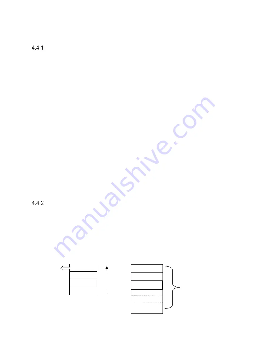
Explanation of Status and Error Indication
When an error occurs the System Status Word is set with the associated Error Code (Register
0x00). When more than one error at the time occurs then the error code is stacked up in order
of its priority.
Each error has an associated error counter. The user may request all error registers for
examination through a request to Register 0x040. MODBUS Function Register 0x40, Reads all
18 Error Registers Sequentially
Status
E-Stack 1
E-Stack 2
E-Stack 3
Counter 1
Counter 2
Counter 18
Counter 3
Reg 0x00
Reg 0x040
Priority


