


MICRONOR AG
MR340-1 DIN Rail Module Controller
Page 26 of 74
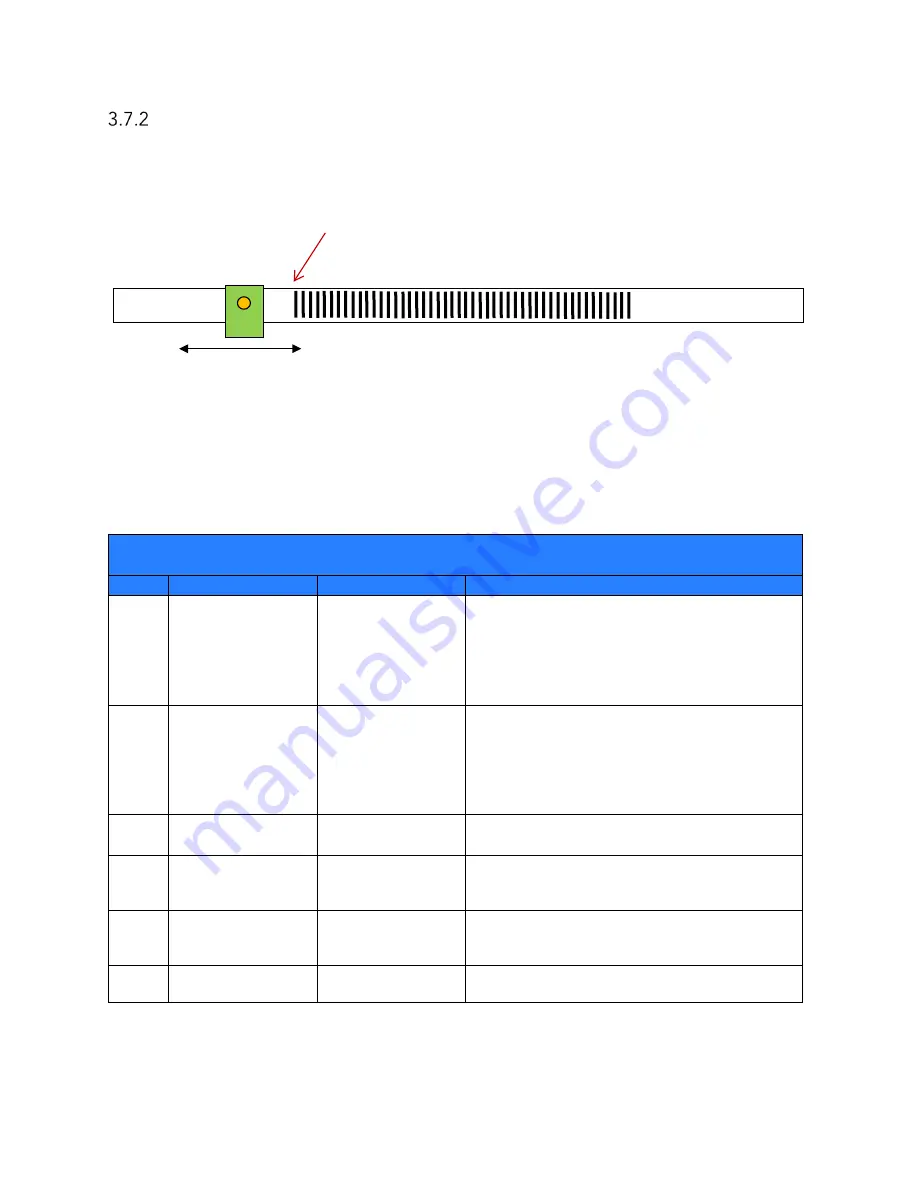
Linear Encoder With Film And Using HOMING Function
Hardware Example: MR343 Linear Encoder, MR340-1 Controller and TD5334 series Film Strip
with 1 or 2 HOMING regions. The diagram below illustrates an application employing a Film
Strip with HOMING region on both sides.
Section 3.5.3 described how to using the HOME technique as an Index for absolute position
monitoring. This type of application would then use the Modbus interface to read absolute
position and speed status. The quadrature outputs can also be used independently.
The following tables describe how to initially configure and operate the MR343 system in this
scenario.
Initial Configuration Sequence
HOMING Linear Encoder Configuration
Step
Command Name Register Address Notes
1
Reset Mode
FC10 0x208
Set to 3 to perform both an Optical Signal
Calibration and reset Position Counter at the
same time. For the Position Counter to
function properly, the user’s actuator will need
to be in the “Homing” zone when the ZERO
Input is pulsed.
2
Preset Value
FC10 0x20A
This will be the Position Counter’s initial value
when the user’s actuator system moves out of
the HOMING region and encounters the first
line on the Encoder Film Strip. Typically user
will set this value to 0 unless another intial
setting is required.
3
Quadrature
Multiplier
FC10 0x211
Set to 0 for 2 counts per line
Set to 1 for 4 counts per line
4
Direction
FC10 0x20B
With this command, the user can set the
preferred direction and “polarity” of the
Position Counter. Set to 0=CW or 1=CCW.
5
Speed Filter
FC10 0x216
For applications monitoring Speed via Modbus,
the user may want to select a value (0-8) to filter
speed results.
6
Save To EEPROM FC05 0x002
Send this command to save all current
parameters to internal EEPROM
Left
HOMING Region
Right
HOMING Region
Working Area
Sensor
Known Home Position


