Micronor MR340-1 Скачать руководство пользователя страница 1


© COPYRIGHT 2018-2022, MICRONOR AG 

REGENSDORF, SWITZERLAND 
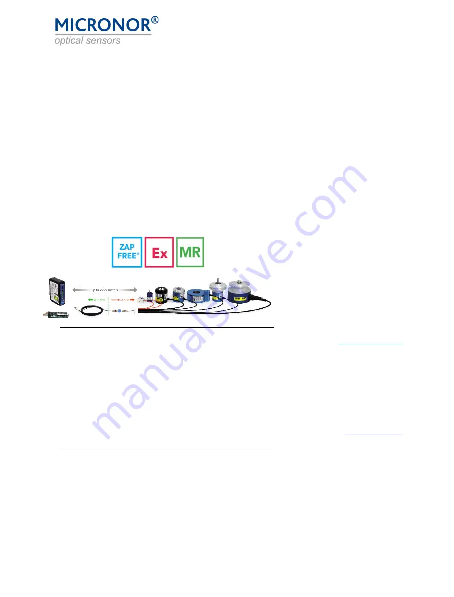
 

MR340-1 

Fiber Optic Incremental Encoder 

DIN Rail Mount Controller 

Instruction Manual 


Includes MR343 Linear Encoder 

Application Information 


Document: 98-0340-12 

Revision: C 


For Sales & Support in North America: 


MICRONOR SENSORS, INC. 

2085 Sperry Ave, Suite A-1 

Ventura, CA 93003 USA 

+1-805-389-6600 

[email protected] 

www.micronor.com 


HQ and Worldwide Support: 


MICRONOR AG 

Pumpwerkstrasse 32  

CH-8105 Regensdorf 

Switzerland 

+41-44-843-4020 

[email protected] 

www.micronor.ch


Notice of Proprietary Rights 


The design concepts and engineering details embodied in this manual, which are the property of MICRONOR AG, 
are to be maintained in strict confidence; no element or detail of this manual is to be spuriously used, nor disclosed, 
without the express written permission of MICRONOR AG.  All rights are reserved.  No part of this publication may 

be reproduced, stored in a retrieval system, or transmitted in any form or by any means, electronic, mechanical, 
photocopying, recording, or otherwise, without prior written permission from MICRONOR AG. 


IMPORTANT NOTE 


The MR340-1 Controller is a rebranding, part number change only 

of the original MR302-1 DIN Controller. Any references to MR302-1 
are applicable to the MR340-1 and vice versa. In addition, the former 
MR303 Linear Encoder is now the MR343, and the former MR304 

Mini Rotary Encoder is now the MR341.  
 

The core dual wavelength 850nm/980nm optical technology of the 
MR302 series replaces the 850nm/1300nm technology of the earlier 
MR320 series, becoming the MR340 series. For more information on 

the MR340 series Controller and Encoders and their compatibility 
with earlier models, please consult Application Note AN127. 

Содержание MR340-1

Страница 1: ...sly used nor disclosed without the express written permission of MICRONOR AG All rights are reserved No part of this publication may be reproduced stored in a retrieval system or transmitted in any form or by any means electronic mechanical photocopying recording or otherwise without prior written permission from MICRONOR AG IMPORTANT NOTE The MR340 1 Controller is a rebranding part number change ...

Страница 2: ...B 3 6 2019 DNH Analog output mode definition corrected in table C 9 12 2022 DNH Changed all MR302 1 DIN Controller references to MR340 1 Changed all MR303 Linear Encoder references to MR343 Changed all MR304 Rotary Encoder references to MR341 Deleted references to obsolete MR302 2 MR340 0 OEM Controller also formerly MR340 0 Updated product ownership to Micronor AG ...

Страница 3: ...rogrammable Analog Output Current or Voltage Connections 17 3 5 How To Install the MR343 Linear Encoder 19 Film Mounting and Handling With MR343 19 Initial Optical Power Level Referencing When Using Film 21 Indexing for Linear Absolute Position 22 3 6 Power up or Periodic Optical Sensitivity Calibration 23 Optical sensistivity calibration for linear sensors 23 Optical sensititivty calibration for ...

Страница 4: ... 52 4 4 Error Handling and Troubleshooting 53 Explanation of Status and Error Handling 53 Explanation of Status and Error Indication 53 Reading The Error Counters 58 5 Specifications 59 5 1 MR340 1 DIN Rail Mount Controller 59 5 2 MR343 Linear Sensor 60 6 ZAPPY 302 SOFTWARE 61 6 1 How To Install and Use Zappy 302 61 6 2 ZAPPY Menu Screens 61 System Functions screen 61 User Functions screen 63 Serv...

Страница 5: ...gure 10 Typical MR340 Encoder Sensor System connections to Motion Control System 14 Figure 11 J1 Connector Pin Assignments 15 Figure 12 Typical MR34X Rotary Encoder System connections to Motor Drive System15 Figure 13 Location of SSI RS485 Modbus RTU and USB Connections 16 Figure 14 J3 Connector Pin Assignments 16 Figure 15 Hirose Plug for J3 Connector 16 Figure 16 Connection for 4 20mA current lo...

Страница 6: ...ong electromagnetic field Surgical robots must perform 100 reliably Aerospace actuators operate in and around other noise generating avionics An all optical non electronic passive solution such as the fiber optic encoder provides completely immunity to such interferences 1 2 Fiber Optic Incremental Sensor The MR340 series is Micronor s 3rd Generation fiber optic incremental encoder system It s inn...

Страница 7: ...MICRONOR AG MR340 1 DIN Rail Module Controller Page 7 of 74 Figure 2 Typical MR340 Encoder System connections to User s Motion Control System ...

Страница 8: ...eport the damage to your shipper immediately 2 Inform MICRONOR 3 Save all shipping cartons Failure to follow this procedure may affect your claim for compensation 2 3 Standard Contents MR340 1 Controller Module MR340 1 Controller Instruction Manual this document one soft copy supplied per shipment when a complete encoder controller system is purchased MR341 MR342 MR344 MR345 MR346 MR348 Rotary Sen...

Страница 9: ...ucts are warranted for the balance of the original warranty period or at least 90 days Limitations of Warranty This warranty does not apply to defects resulting from unauthorized modification or misuse of any product or part This warranty also does not apply to Fiber Optic Connector interfaces fuses or AC line cords This warranty is in lieu of all other warranties expressed or implied including an...

Страница 10: ...d of both non metallic and non ferrous materials The sensor is safe for use within or around MRI equipment or within other extreme electromagnetic fields Figure 3 MR340 Controller works with MR343 Linear and all MR34X Rotary Sensors When installing the sensor be careful not to bend the fiber excessively It is recommended to keep the minimum bend radius 25mm 1 or larger Ensure the fiber outlet at t...

Страница 11: ...ler unit mounts on standard 35mm DIN rail or it can be screw mounted to a wall or cabinet For DIN rail mounting insert clip to the unit and then clip onto DIN rail by bending the clip tabs toward the enclosure When screw mounting remove clip from enclosure and use screws to affix clip to the wall and then clip enclosure onto the plastic clip Both mounting schemes are shown below in Figure 3 and Fi...

Страница 12: ...he connector on the cable and open the spring loaded cover of the receptacle on the controller Insert the LC connector as shown There should be a positive click when the connector is engaged properly Do not force the Fiber Optic Connector Figure 7 Connecting Sensor to Controller Optical Interface This is the same fiber used in local area networks LANs The cable ends must be terminated with high qu...

Страница 13: ...pt clean from dust and other contaminants Always keep unmated connectors covered with an appropriate dust cap Do not touch the connector ends Before mating clean BOTH connector ends as shown below in Figure 6 and Figure 7 Figure 9 Clean Optical Plug with supplied Clean Wipes Figure 8 Clean Receptacle with the supplied Cleaning Stick ...

Страница 14: ... 12V or 24V signal levels The factory setting is 5V Consult section 8 1 User Parameter Settings If the sensor system is used to display position or speed an analog panel meter may be connected to the analog signal output SIG SIG The output can be programmed for either Voltage 10V or current 4 20mA as well as freely scaled to indicate either position or speed Consult section 8 1 User Parameter Sett...

Страница 15: ...User Selectable Analog Output 10V or 4 20mA 6 SIG 7 A User Selectable A B Quadrature Output Level 5V 12V 24V 8 A 9 B 10 B Figure 11 J1 Connector Pin Assignments Interfacing With a Motor Drive One common application for any encoder is to provide position and velocity information to a servo drive In this example the A B quadrature signals are connected directly to the encoder inputs of the servo dri...

Страница 16: ... 10P C 50 Digikey P N H11343 ND Mouser P N 798 324010PC50 Recommended Cable Tensility International P N 30 00534 Digikey P N T1355 5 ND Micronor P N MR430 99 01 available separately is a pre assembled pigtail assembly with 1m pigtail Figure 15 Hirose Plug for J3 Connector RS485 via J3 SSI via J3 MR430 99 01 Color Code Pin Function Function Color 1 5V 5V Brown 2 RS422 RCV input Red 3 RS422 RCV inpu...

Страница 17: ... supply Programmable Analog Output Current or Voltage Connections The analog output of the MR340 1 Controller is user settable for either current or voltage output This section assumes that the user has already programmed the analog output for one of these modes using the supplied ZAPPY 302 configuration software An internal relay configures the function of terminals 5 and 6 to either current outp...

Страница 18: ...g wiring resistance should be less than Rbmax 24V 7 5V 20mA 825ohm In practice the burden resistance should not exceed 500 ohms CAUTION Before connecting a voltage source to the Current output make sure to set this parameter to current output Otherwise the voltage output will attempt to drive against the applied voltage source Voltage Output Connection The current output of the MR340 1 controller ...

Страница 19: ...ng within the slit Emulsion side of film must face side where the fiber enters the sensor Be careful when handling film to not leave fingerprints After film strip is inserted into sensor either use the supplied clip or cover to secure film and maintain proper alignment Figure 18 Positioning film inside MR343 sensor To protect the film from scratches where the light senses the lines the assembly ha...

Страница 20: ... can be seen in Figure 15 positional accuracy is given by the film itself and the shape of the light beam The film is made accurately to within 3µm The absolute edge accuracy is approx 25 of the slit width With the design as shown above the very worst case deviation is 50µm maximum Typically 25µm can be expected Thermal expansion of the film tape is typically 22µm m C With the temperature variatio...

Страница 21: ... the controller for 10 seconds The PWR LED will blink while the calibration is being performed After 10 seconds the STATUS LED will blink shortly then release the button NOTE The calibration sequence may also be initiated via Modbus command The internal procedure within the controller is as follows The input amplifiers are being set to a known sensitivity gain then the laser power for each channel...

Страница 22: ...t reference count corresponding to the absolute known position to the start of the first line is loaded into the position counter The servo motor then drives towards the start of the working area The position counter will start counting as soon as the first line is encountered Note The number examples above are when x2 multiplier is used The left and right homing positions are provided to the serv...

Страница 23: ...stivity calibration for linear sensors At power up it is recommended to move the MR343 sensor head to a clear area of the film strip and then initiate a 24V logic pulse of 100ms to 1sec duration to the HOMING Input input J1 Pin 3 Instead of a 24V logic pulse on J1 15 the sequence may be initiated using Modbus FC05 0x007 Register 0x208 must be configured to 0x03 in order for the above procedure to ...

Страница 24: ...0 1 Controller For Rotary Applications Using Quadrature Outputs Only For systems that will use the A B quadrature outputs only the user need only optically connect the encoder to the controller and go Optical Signal Calibration occurs automatically while the encoder is turning Before initial use it is recommended to connect the optical link all segments full length first and perform an Optical Sig...

Страница 25: ...et Value FC10 0x20A This will be the Position Counter value when the user s actuator system is in the reference position Typically the user will set this value to 0 unless another initial setting is required 3 Quadrature Multiplier FC10 0x211 Set to 0 for 2 counts per line Set to 1 for 4 counts per line 4 Direction FC10 0x20B With this command the user can set the preferred direction and polarity ...

Страница 26: ...orm both an Optical Signal Calibration and reset Position Counter at the same time For the Position Counter to function properly the user s actuator will need to be in the Homing zone when the ZERO Input is pulsed 2 Preset Value FC10 0x20A This will be the Position Counter s initial value when the user s actuator system moves out of the HOMING region and encounters the first line on the Encoder Fi...

Страница 27: ...egister 0x0001 250 Counter Register is now set at 250 Register 0x0208 3 Reset Mode Register 0x0209 250 Preset Register This value will be in the counter after the reset Register 0x020B 1 Turn or Count Direction Note Executing the calibration will automatically save all current parameter register content to EEPROM Normal Power Up Sequence HOMING Linear Encoder Step Command Name Action Notes 1 User ...

Страница 28: ...uator must be at the reference position when ZERO Input is pulsed 2 Preset Value FC10 0x20A This will be the Position Counter value when the actuator is at the reference position Typically the user will set this value to 0 unless another initial setting is required 3 Quadrature Multiplier FC10 0x211 Set to 0 for 2 counts per line Set to 1 for 4 counts per line 4 Direction FC10 0x20B With this comm...

Страница 29: ...eference position 2 ZERO Input Pulse ZERO Input or send FC05 0x007 command Controller will reset Position Counter to the Preset Value 3 System ready Read Position Count and Speed via Modbus Quadrature outputs can also be used independently 4 An automatic Optical Calibration is performed whenever the sensor sweeps through the active area at minimum speed of 0 2 meters second ...

Страница 30: ... Start Bit 8 Data Bits 1 Stop Bit no parity The protocol is Modbus compatible and thus the protocol includes a node address That is so that the PCB could be integrated into larger systems using a number of Modbus slaves Factory Standard ModBus Address is set to 235 Hexadecimal 0xEB Note The MR340 1 Controller requires a RS485 422 to RS232 converter for interfacing to the RS232 COM Port of a comput...

Страница 31: ...of 74 2 Wire Circuit Half Duplex D1 RX TX is pulled up to 5V D0 RX TX is pulled down to GND Recommended resistor is 1KΩ 4 Wire Circuit Full Duplex TXD1 TX and RXD1 Rx are pulled up to 5V TXD0 TX and RXD0 RX are pulled down to GND Recommended resistor is 1KΩ ...

Страница 32: ... to be on the machine Please refer to section 6 for detailed information Unless you plan to connect the MR340 1 to your own PLC or computer equipment for real time data retrieval you do not need to become familiar with the detailed communications protocol described herein Framing Message frames are separated by a silent interval of at least 3 5 character times If a silent interval of more than 1 5...

Страница 33: ...ese functions before using Register Address Register Number Name regs Range Description 0x000 0x001 System Status 1 n a Returns the system status A 0x0000 means all is ok See status information 0x001 0x002 Get Encoder Count 2 n a Returns or sets position count as a 32 bit integer 0x003 0x004 Get Speed 2 n a Returns the speed information as a 32 bit signed in 1 100 rpm 0x004 0x005 reserved 2 n a 0x...

Страница 34: ...alibration value for voltage output 0x133 0x134 Voltage Gain Pos Factory Calibration 1 128 127 Factory use only do NOT write to it Hardware calibration value for voltage output 0x134 0x135 Voltage Gain Neg Factory Calibration 1 128 127 Factory use only do NOT write to it Hardware calibration value for voltage output 0x135 0x136 Current Gain Factory Calibration 1 128 127 Factory use only do NOT wri...

Страница 35: ...0x140 0x141 Amplifier Gain CHA 1 0 255 Controls the gain of Channel A amplifier 0 is max gain 255 is minimum gain 0x141 0x142 Amplifier Offset CHA 1 0 255 Controls the input offset of Channel A amplifier This is set at the factory only Should typically be a low number of less than 20 0x142 0x143 Amplifier Gain CHB 1 0 255 Controls the gain of Channel B amplifier 0 is max gain 255 is minimum gain 0...

Страница 36: ...r SPEED bipolar output range 0 12 24 mA where 12mA represents 0rpm 1 For SPEED unipolar output range 0 24mA where 0mA represents 0rpm 2 For SPEED unipolar output range 4 24mA where 4mA represents 0rpm 3 For POSITION bipolar output range 0 12 24mA where 12mA represents zero position counter value 4 For POSITION unipolar 0 24mA range where 0mA represents zero position counter value 5 For POSITION un...

Страница 37: ...e reading 1 when CCW then outputs are positive reading 0x211 0x212 Quadrature Signal Multiplier 1 0 1 0 counts cycles x2 1 counts cycles x4 0x214 0x213 Quadrature Voltage 1 0 1 Set the line driver output voltage 0 disabled 1 5V 2 12V 3 24V 0x215 0x216 Analog Output Select 1 0 1 Select voltage or current output 0 Voltage 1 Current 4 20mA with 3mA overrange 0x216 0x217 Speed Filter 1 0 8 Sets the sp...

Страница 38: ...put 0x304 0x305 n a 1 n a engineering measurement output 0x305 0x306 n a n a 0x306 0x307 n a n a 0x307 0x308 n a n a 0x330 0x331 POT 1A 1 0 255 Pot U4A CHA offset ENGWRT only 0x331 0x332 POT 1B 1 0 255 Pot U4B CHA gain ENGWRT only 0x332 0x333 POT 1C 1 0 255 Pot U4C CHB offset ENGWRT only 0x333 0x334 POT 1D 1 0 255 Pot U4D CHB offset ENGWRT only 0x400 0x401 Device Name 4 n a Returns the ASCII strin...

Страница 39: ... counters to 0 Same as in power up 0x007 0x008 Emulate ZERO Input This software emulates external ZERO input pulse whose response is determined by the Reset Mode 0x208 setting MODBUS Message Format The following is a brief overview of the detailed byte by byte messaging of the ModBus protocol Please consult the Modbus standards for more detailed information When using appropriate drivers the user ...

Страница 40: ...The user may reset or preset the counter to any value within a full 32 bit range Range is signed 32bit The sign bit indicates that the encoder is turning Counter Clockwise CCW looking at the encoder from the shaft end The encoder Counter is volatile and will be reset once electrical power is lost MODBUS commands Speed RPM output Register 0x003 Register Address 0x003 Register Count 2 Speed is calcu...

Страница 41: ...egister 0x200 Register Address 0x200 The setting of the mode determines how the speed in rpm or position count will be output as analog voltage to the voltage output Default Mode 0 SPEED Modes Description 0 Output corresponds to actual RPM where CCW rotation is negative voltage The voltage output range is 0V to 10V when the encoder rotates CW Overrange extends 0 4V beyond 10V The voltage output ra...

Страница 42: ...er Address 0x201 The voltage scale can be set by the user to track SPEED or POSITIOIN Example With Voltage Mode set to 0 a Voltage Scale setting of 1000 will provide a full scale 10V output for 1000RPM CW or 10000V output for 1000RPM CCW Faster speeds will linearly extend from 10V until peaking at approx 10 4V Range Description 10 100 000 SPEED In SPEED mode a Voltage Scale setting of X establishe...

Страница 43: ...hen setting the filter value to n an approximate time constant of n ms can be expected The MR320 measures the period between passing slits of the code wheel When the encoder is turning slow so that the elapsed time between slits is larger than 1ms then the low pass algorithm is changed and the time constant becomes larger as the encoder turns slower This adaptive filtering algorithm provides for a...

Страница 44: ...utput over 4mA to 12mA to 20mA where 12mA is equal to 0 RPM CW rotation from 0RPM to Current Scale RPM corresponds to 12mA to 20mA Overrange extends from 20mA to 23mA maximum CCW rotation from 0RPM to Current Scale RPM corresponds to 12mA to 4mA Overrange extends from 4mA to 0mA minimum 1 Unipolar output range of 0 24mA where 0mA represents 0RPM regardless of direction 2 Unipolar output range of 4...

Страница 45: ... corresponds to 12mA to 20mA Overrange extends from 20mA to 23mA maximum CCW rotation from 0 counter value to negative Current Scale setting corresponds to 12mA to 4mA Overrange extends from 4mA to 0mA minimum 4 Unipolar output range of 0 24mA representing the absolute value of the Counter 0mA represents the zero position and 20mA corresponds to the Current Scale setting regardless of direction or...

Страница 46: ...esents zero and negative position and 20mA corresponds to Current Scale Overrange extends over 20 23mA In all cases there is an overrange capability of 4mA to 23mA Use the MODE command to select the desired output mode Current Output Cautions Current outputs are inherently short circuit proof The maximum burden resistance for the MR340 is 500 Ohms with a 24V power supply At 23mA that represents a ...

Страница 47: ...user configurable low pass filter exists to allow smoothing of the calculated RPM based on user constants It is the filtered RPM that is output to the voltage DAC The 3dB filter point is programmable from 500Hz no filtering down to 1Hz Af Filtered analog output value Af t 1 Previous filtered analog output value n Filter constant in 2nmilliseconds Am new analog unfiltered value The output is update...

Страница 48: ...are logically OR d and all or none of the above functions apply when the external input goes high Modes Description 000b No action with rising edge of external input 001b RESET encoder counter to Preset value stored in parameter 0x209 011b Reset encoder counter and initiate a calibration cycle This maybe a useful function in conjunction with a linear filmstrip encoder When the sensor is at a known...

Страница 49: ...he value is 32bit signed MODBUS commands Quadrature Edge Multiplier Register 0x211 Register Address 0x211 The internal position counter can be set to advance with each edge on the channel A signals x2 or advance on all transitions x4 If an encoder has a resolution of 512ppr then a total of 512 x 4 2048 counts are available Modes Description 0 X2 counting 1 X4 counting Be sure to set the output sca...

Страница 50: ... e a positive speed is indicated by a positive voltage When this direction parameter is set to 1 then all directional outputs are reversed This may become useful when an encoder cannot be installed to turn in the CW direction within a system definition for CW being positive speed or positive position Modes Description 0 Analog outputs and digital read out follow CW direction 1 Analog outputs and d...

Страница 51: ...ister Address 0x215 T he analog output on J1 is either a voltage or a current 4 20mA output This parameter selects which mode the output will operate at 0 Voltage Output 1 Current 4 20mA Output CAUTION Connecting a voltage source to this output be sure to set this parameter to current output Otherwise the voltage output will attempt to drive against the applied voltage source This parameter is pro...

Страница 52: ...tored parameters will be lost when power is removed to the MR340 Controller In addition to checksums all parameters are stored twice internally and when retrieved both copies are compared and only restored when there is a match or when it is determined that there is one good copy of the parameter To store parameters into the EEPROM initiate Modbus command FC5 2 All parameters in EEPROM are always ...

Страница 53: ... Restore value out of range 4 Communication Errors Communication errors are flagged by the underlying Modbus drivers However Modbus standard does not specify a data integrity test This is where the MR340 allows the user to query the Status byte after each transmission to verify if the provided data was within the appropriate range etc Explanation of Status and Error Indication When an error occurs...

Страница 54: ...ror in the Status byte If there are more errors stacked up then the next highest priority will be displayed Some errors are cleared as soon as normal operation is established For instance when the sensor is disconnected or a high loss in the optical connection occurs an error is reported and the PWR LED will blink When the optical connection is re established then the error will clear itself witho...

Страница 55: ...nor ZAPPY software software or recycle Power Blink 5x code 259 EEPROM Checksum Low Bank checksum failure low bank 1 One set of data in EEPROM shows a bad checksum Firmware automatically corrects the error n a n a 260 EEPROM Checksum High Bank checksum failure low bank 1 One set of data in EEPROM shows a bad checksum Firmware automatically corrects the error n a n a 261 EEPROM Bad Value One or more...

Страница 56: ...ontaminated connectors Or long link lengths in excess of 1 5km Check your fiber optic link The one way loss should be less than 5dB self clear examine error counter for a history of this error Blink 2x code 772 Receiver gets excessive optical power 2 If this occurs the VCSEL optical power needs to be reduced This is accomplished using ZAPPY software An optical attenuator could also be inserted int...

Страница 57: ...egister 1 Check your software for correct register addressing See user manual with address table Note This controller does not allow to read across multiple registers self clear after one blink Blink 1x once 1028 CMD Wrong Device Addr The device address sent was not matching the address of this unit 1 The MR330 controller has on fixed address at 235 If you are not sure what the address is talk to ...

Страница 58: ...e sequence of registers is according to the error number in Table 1 in ascending order Each register is a 16 bit word If the most significant bit is set to a logical one this indicates that there is an active error residing in the Status stack The remaining 15 bits indicate the number of errors that occurred since power was applied to the unit The user may clear all error counters by issuing Funct...

Страница 59: ...ax burden resistance 500Ω 24V Supply 0 25 of Full Scale 50µA Range 10V Max current 5mA 2kΩ load Short circuit 5s 0 25 of Full Scale 25mV Power Supply 24 VDC 5 50mA typical During power up external power supply shall be capable of 100mA inrush current Optical Interface Specification Connector LC Duplex PC Polish Fiber Type Duplex 62 5 125µm 0 275NA OM1 Multimode Fiber Maximum Link Loss Maximum 12dB...

Страница 60: ... Specification Connectior LC Duplex PC Polish Fiber Type Duplex 62 5 125µm 0 275NA OM1 Multimode Fiber Pigtail Length 1 5 to 10m Maximum Link Loss Consult Controller specifications Physical Materials Acetal Ceramic Glass No ferromagnetic metals or conductive materials are used Dimension 30 x 28 x 15mm 1 18 x 1 10 x 0 59 inches Weight 10g 0 3oz Without cable Cable weight 10g m Environmental Operati...

Страница 61: ...t will automatically find the MR302 PCB if properly connected to the PC via its Windows assigned virtual comm port 3 ZAPPY will open up to the System Functions screen as shown in Figure 17 When parameter s are changed and you want to keep them saved in the PCB you must click the Set EEPROM button Observe caution when changing serial interface parameters The change will only take effect after a pow...

Страница 62: ...MICRONOR AG MR340 1 DIN Rail Module Controller Page 62 of 74 Figure 21 ZAPPY System Functions screen ...

Страница 63: ...tions screen In the User Functions screen buttons are provided to read from and write to the various Controller registers These buttons emulate the corresponding Modbus commands Here the user can actively operate the encoder system and oberve system status Position Counter Speed etc Figure 22 ZAPPY User Functions screen ...

Страница 64: ...age allows the user to observe inner workings of the unit Get ADC readings shows the user what the analog optical signal levels are The minimum and maximum voltage level for each channel are given The built in A D converter is 10 bit and referenced to 3 3V The voltage can be calculated V 3 3V Count 1024 Hence 640 counts equals 2 06V The peak level of the encoder signal is regulated to be 2V or 640...

Страница 65: ...ontroller This is helpful when writing interface software It also lets the user save and load given set of parameters so that all controllers can be programmed with the same set of parameters When discussing issues with the factory it is recommended to save a Diagnostics Report file and send to the factory This will speed up the trouble shooting process for the factory engineer When outputting a D...

Страница 66: ... the A and he B track on the sensor wheel The light of each beam is now modulated with the 90 phase shift based on the turning direction of sensor wheel The modulated light is coupled back into the optical receive fiber guiding the light back to the receiver in the controller module The two colors of light are returned to the controller converted back into an electrical signal amplified to a known...

Страница 67: ...ntrol over the ON OFF state and the power level of the VCSEL diodes During manufacturing the optical power level is calibrated to the desired value Within ZAPPY software this level is accessible via Modbus commands 0x144 and 0x145 The receiver is comprised of a dichroic beam splitter which separates the two wavelengths The light of each wavelength is converted into an electrical current by photo d...

Страница 68: ...ownload from the Micronor web site REFLASH MR302 Install this software on your PC Request from Micronor or the authorized Service representative the new Firmware MR302 DIN_V1pxpxx hex Note Only controllers with Firmware Version 1 1 22 or higher are capable of being reflashed Setup the MR340 1 as shown to the left Connect the USB cable to the PC Power the unit with a suitable 24V DC supply Prepare ...

Страница 69: ...ity of the hex file Caution Make sure it is the hex file provided to you by Micronor It is possible to flash any valid hex file However at that point the MR340 1 unit will no longer be functional and may take internal damage Click Start If connection to the MR340 1 unit has been successfully established then the software prompts to push hold the reset button on the MR340 1 unit Push the button and...

Страница 70: ...age 70 of 74 Upon release of the button the firmware is being transmitted and written to the Flash Memory of the MR340 1 unit The green progress bar indicates the writing progress When the write is successfully completed you may disconnected the unit ...

Страница 71: ...ort Select Hex File with valid Firmware Double Click the Factory Flash label Turn 24V power OFF Push the MR340 1 Reset button and hold Turn 24V Power ON keep button pressed Wait for 5 seconds and observe the red and green LED blink in alternating fashion Release the Reset button Within 3 seconds time click the Write Button on the software The software will start transmitting and writing the new fi...

Страница 72: ...MICRONOR AG MR340 1 DIN Rail Module Controller Page 72 of 74 9 Mechanical Reference Drawings These reference drawings can be found on the following pages 9 1 MR340 1 Controller 9 2 MR343 Linear Sensor ...

Страница 73: ...9 DUPLEX LC CONNECTOR 89 10 3 51 89 1 3 51 MINIMUM REQUIRED DISTANCE FOR FIBER OPTIC CONNECTOR 3 5 89 NOT SHOWN TO SCALE UNIT MOUNTS ONTO STANDARD 35MM DIN RAIL 63 50 2 50 2X 5 08 0 20 FOR MOUNTING J3 SERIAL RS485 ModBus J2 USB 1 MAKE SURE FIBER OPTIC PORT IS COVERED WHEN NOT IN USE NOTES UNLESS OTHERWISE SPECIFIED ORDERING CODE MR340 1 TERMINAL DESCRIPTION 1 24VDC POWER SUPPLY 50MA TYP 2 GND 3 IN...

Страница 74: ...0 580 22 86 0 900 22 86 0 900 27 94 1 100 29 46 1 160 4X 2 39 0 094 THRU OPTICAL INTERFACE 4 57 0 180 RETAINING CLIP ORDERING CODE MR343 B 400 C 03 OPTICAL PIGTAIL LENGTH IN METER 1R5 1 5 METER 03 3 METER 05 5 METER 10 10 METER OPTICAL INTERFACE C LC DUPLEX CONSTRUCTION B MRI SAFE RESOLUTION 400 400mm PULSE TO PULSE EXAMPLE MR343 B400C03 STANDARD MRI SAFE LINEAR ENCODER WITH 400mm RESOLUTION 3M PI...

Отзывы: