background image

XTreme-EMS Operating Manual

Page 71

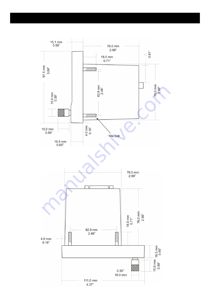
12.2 Side view (Version 1)

12.3 Top view (Version 1)

Содержание XTreme - EMS

Страница 1: ...wide viewing angle 4 3 1000cd m2 sunlight readable color display All engine sensors are connected to a RDAC Remote data acquisition unit which is normally mounted behind the firewall of the aircraft a...

Страница 2: ...for quick item selection and user setups Sunrise Sunset calculator Firmware upgrades via SD Card 1 year limited warranty 2x RS232 communication ports UL Power Interface External GPS receiver 1x CAN co...

Страница 3: ...pressure senders e g UMA Temperature can be measured using standard automotive resistive senders e g VDO Westach as well as the MGL Avionics precision LM335 semiconductor sensor High accuracy Built i...

Страница 4: ...plays engine information from the UL Power ECU Engine Control Unit via the RS232 port The Xtreme EMS has a dedicated UL Power ECU display screen Displays warning messages from the UL Power ECU Rotax 9...

Страница 5: ...r the previous display screen Press to advance to the next display screen D15 Input connector Power Communications OAT probe and alarm output Fits into a standard 3 1 8 80mm instrument Panel hole Metr...

Страница 6: ...EMS Operating Manual Page 6 3 Display Screens Press the left or right most soft keys to cycle through the display screens EMS DISPLAY GPS DISPLAY External GPS receiver required CHECKLIST INFORMATION D...

Страница 7: ...Hobbs time can be set to the current known engine time in the TIMERS SETUP menu MAINT Maintenance Timer This timer is set in engine hours and it will count down to zero when the engine RPM is greater...

Страница 8: ...gine running time for the purpose of the maintenance timer is defined as the run time where the engine RPM is greater than the HOBBS MINIMUM RPM value as set in the TIMERS SETUP 3 1 2 RPM Rotor MAP di...

Страница 9: ...the normal display after 60 seconds 3 1 3 Volts OAT Oil Temperature Pressure Current and Auxiliary Analog section This section displays the supply voltage OAT oil temperature oil pressure as well as t...

Страница 10: ...w single fuel level sender single calculated tank 3 1 4 4 Single Differential Summed fuel flow single fuel level sender single calculated tank These modes are nice for multiple fuel tanks whereby one...

Страница 11: ...level indicator This mode is displayed if either fuel level 1 or fuel level 2 is selected Both fuel flow senders are disabled 3 1 4 8 Dual tank level indicator This mode is displayed if both fuel leve...

Страница 12: ...e fuel pressure bar will be displayed when the fuel pressure has been enabled in the menu system The below picture illustrates a single physical fuel tank with a single flow and fuel pressure enabled...

Страница 13: ...e indicated the temperature value if HIGHEST is selected The EGT highlight color is magenta and the CHT color is cyan EGT CHT Trend graph The EGT CHT trend displays can be accessed by pressing the 2nd...

Страница 14: ...FUEL REFILL Select this menu option to refill a calculated fuel tank Press the FULL soft key for a quick fill to the full reading in the tank setup menu Press the EXIT soft key when done CRUISE SPEED...

Страница 15: ...ferentiate it from the normal operating mode As the fuel mixture is slowly leaned past the point at which the temperature begins to drop by more than 10 C 15 F the absolute EGT temperatures will chang...

Страница 16: ...e timer and the ON OFF soft key to enable or disable the timer MIN MAX Select this menu option to display the maximum and minimum captured values Press the RESET soft key to reset the min max values t...

Страница 17: ...netic variation is shown 3 4 GPS Quick Select Menu System Press the rotary control when the GPS screen is shown to access the GPS quick select menu BACKLIGHT Select this menu option to adjust the back...

Страница 18: ...on SD card The BMP to MIF program is used to convert images in Windows BMP format to MIF format You can use this program to make your own startup screen Splash screen and graphic information pages The...

Страница 19: ...The number of checklists that can be stored and displayed depends on the size of the SD card 3 6 Information Checklist Quick Select Menu System Press the rotary control when the Info Checklist screen...

Страница 20: ...s the rotary control knob again Use the rotary control to navigate the menu system 4 1 Menu Sub Bar Use the menu sub bar for quick menu navigation Select the soft key directly under the text to activa...

Страница 21: ...FLIGHT CSV The exported flight log is exported in a CSV Comma Separated Values file format and can be imported into programs such as Microsoft Excel and Libre VIEW FLIGHT LOG This allows the pilot to...

Страница 22: ...result in the end of a flight and a logbook entry FLIGHT DETECT MINIMUM RPM1 Automatic mode only Enter the minimum RPM 1 threshold that will start a new flight log entry FLIGHT DETECT MINIMUM RPM2 Aut...

Страница 23: ...XTreme EMS Operating Manual Page 23 4 3 EMS Setup...

Страница 24: ...ion RPM DISPLAY MIN Select the minimum RPM that you want the RPM dial to show This can give you increased display resolution HIGH ALARM This enables or disables the RPM high alarm HIGH ALARM Enter the...

Страница 25: ...uld generate one pulse for every two revolutions per cylinder A four cylinder automotive four stroke engine would thus generate 2 pulses per revolution A typical Rotax DCDI two stroke engine would gen...

Страница 26: ...the high alarm must be activated Any Rotor RPM value above this value will activate the alarm HIGH CAUTION Enter the RPM value for the high caution This is the lower value of the upper yellow band LO...

Страница 27: ...o suit your RPM 2 channel so you can identify it easily POSITION Select which side of the analog dials the RPM 1 RPM 2 must be displayed on Style Select this menu option to change the graphic style of...

Страница 28: ...aximum number of EGT and CHT channels that can be displayed is 12 EGT CHT DISPLAY MAX Select the maximum temperature that you want the EGT CHT bargraph to show This can give you increased display reso...

Страница 29: ...ING can be selected If HIGHEST is selected then the current highest thermocouple temperature is displayed If SCANNING is selected then the unit will cycle through each thermocouple at the time specifi...

Страница 30: ...nder supplied by MGL Avionics has a K Factor of 7000 in the low flow mode jet installed and 1330 for the high flow mode no jet installed The Flowscan 201A 6 has a K Factor of 8454 You can use the K Fa...

Страница 31: ...our desired minimum fuel value that you would like to trigger the fuel low alarm LOW CAUTION Enter the fuel level value for the low fuel caution CALIBRATE TANK The fuel level sender needs to be calibr...

Страница 32: ...position then you have a problem Please check your wiring according to the installation section of this manual You should expect the number to change in the region of at least 20 to 60 counts per cali...

Страница 33: ...f mind during cross county flights Notes on Slope error Sender value is a value determined by the XTreme It is used to calculate fuel level fuel endurance estimate and current range estimate The fuel...

Страница 34: ...lect VDO for VDO resistive senders USER for a custom sender MODEL Select which VDO pressure sender you are using A selection between a VDO 2 5 or 10 Bar can be selected If the VOLTAGE pressure sender...

Страница 35: ...ou increased display resolution DISPLAY MIN Select the minimum pressure that you want the oil pressure bargraph to This can give you increased display resolution HIGH ALARM This enables or disables th...

Страница 36: ...fold bargraph in the EMS display to show This can give you increased display resolution HIGH ALARM This enables or disables the manifold pressure high alarm HIGH ALARM Enter the pressure threshold for...

Страница 37: ...r manifold pressure can change its reading MAP CALIBRATION FACTOR The sender in the RDAC is shipped uncalibrated To calibrate the manifold pressure compare and adjust the calibration factor until the...

Страница 38: ...e sender If the sender is set to USER CALIBRATE SENDER If the sender type is set to USER then use this menu option to calibrate your temperature sender See section 4 4 9 for more information If the se...

Страница 39: ...tion HIGH ALARM This enables or disables the temperature high alarm HIGH ALARM Enter the temperature threshold for when the high alarm must be activated Any temperature above this value will activate...

Страница 40: ...nders USER for a custom sender MODEL Select which VDO pressure sender you are using A selection between a VDO 2 5 or 10 Bar can be selected If the VOLTAGE pressure sender is selected Sender Select the...

Страница 41: ...sure that you want the oil pressure bargraph to show This can give you increased display resolution DISPLAY MIN Select the minimum pressure that you want the oil pressure bargraph to This can give you...

Страница 42: ...tions are PRESSURE TEMPERATURE CURRENT or OFF If the PRESSURE function is selected TYPE Select if you are using a resistive 4 20mA or 0 5V output pressure sender If the RESISTIVE pressure sender is se...

Страница 43: ...r is selected CALIBRATE SENDER If the sender type is set to USER then use this menu option to calibrate your pressure sender See section 4 4 9 for more information LABEL Enter a label to suit your tem...

Страница 44: ...re sender LM335 for a MGL precision temperature sender or USER for a custom sender The XTreme has a built in linearization curve for a standard 50 C to 150 C VDO resistive sender Westach senders and t...

Страница 45: ...W CAUTION Enter the temperature value for the low caution This is the upper value of the lower yellow band LOW ALARM This enables or disables the temperature low alarm LOW ALARM Enter the temperature...

Страница 46: ...nt value for the low caution This is the upper value of the lower yellow band LOW ALARM This enables or disables the current low alarm LOW ALARM Enter the current threshold for when the low alarm must...

Страница 47: ...high alarm must be activated Any voltage above this value will activate the alarm HIGH CAUTION Enter the voltage for the high caution This is the lower value of the upper yellow band LOW CAUTION Enter...

Страница 48: ...LARM Enter the current threshold for when the high alarm must be activated Any current above this value will activate the alarm HIGH CAUTION Enter the current value for the high caution This is the lo...

Страница 49: ...rent is reading correctly It will be best if a multimeter can be inserted in series with the current supplying conductor and the gain calibration adjusted until the Xtreme EMS matches that of the mult...

Страница 50: ...resolution HIGH ALARM This enables or disables the OAT high alarm HIGH ALARM Enter the temperature threshold for when the high alarm must be activated Any temperature above this value will activate th...

Страница 51: ...onnected to the Xtreme EMS Select NONE for standard functionality ROTAX 912is or UL POWER 4 3 13 1 ROTAX 912IS Setup MGL Avionics RDAC CAN required The Rotax ECU transmits various status messages Thes...

Страница 52: ...Coolant Temperature This is remapped to ANALOG AUX1 FUNCTION TEMPERATURE SENDER LM335 LM335 0 EGT 1 2 3 4 EGT CHANNELS 4 Throttle Position 0 100 can be viewed in the ECU Setup ROTAX 912iS section Engi...

Страница 53: ...er you want the temperature to be displayed in degrees Celcius C or in degrees Fahrenheit F UL Power display screen A dedicated display screen will be shown when the UL Power is selected for the ECU t...

Страница 54: ...il Temperature Max 120 C 248 F Min 50 C 122 F Normal between 80 C and 100 C 175 F 212 F Fuel Pressure max 3 8 bar 55psi normal 3 bar 43 5 psi minimum 2 4 bar 35 psi MAP Max 1 1 bar 33 inch kg Min 0 3...

Страница 55: ...the external GPS receiver you are using POSITION FORMAT Select the display format of the GPS latitude and longitude ALTITUDE UNIT Select the unit of the altitude display COG Select if you want the CO...

Страница 56: ...allows you to set the engine Hobbs meter to any value Typically you would use this function to set the Hobbs meter to the current known engine time Use the rotary control to change the value Press th...

Страница 57: ...he timer when you have serviced your engine A typical time might be 50 hours This function allows you to set an engine maintenance timer This timer is set in engine hours and it will count down to zer...

Страница 58: ...OMATIC OR MANUAL FLIGHT DETECT MODE The UL Power ECU data is also recorded if available DATA RECORDING ON Selecting ON will enable the data recording functionality Output file format CSV Comma Separat...

Страница 59: ...psi Temperature in Degrees C Current in A Manifold Pressure Manifold pressure in mBar Current Current in A CJC Cold junction temperature in Degrees Celsius TC1 Thermocouple channel 1 in Degrees Celsi...

Страница 60: ...l Level 2 in Liters Fuel Pressure Fuel pressure in psi OAT OAT temperature in Degrees Celsius Latitude Latitude in decimal degrees Negative is South Longitude Longitude in decimal degrees Negative is...

Страница 61: ...ferring the settings on the instrument itself A file called XTREME2 EMS will be created in the root directory of the SD card This function is also used to save your settings during firmware upgrades R...

Страница 62: ...XTreme EMS Operating Manual Page 62 INFORMATION This displays information about the Xtreme EMS unit 4 8 ADC Values These values are mainly used for debugging purposes...

Страница 63: ...this program to make your own startup screen Splash screen and graphic information display screens The color depth is limited to 256 colors Run the BMP image to MIF format converter program Load an i...

Страница 64: ...n s that activated the alarm no longer exist The alarm output can be used to switch an external alarm indicator The external alarm switch is an open collector transistor switch to ground with a maximu...

Страница 65: ...anel user adjustable Dimensions Fits standard 3 1 8 80mm instrument hole See section 12 for dimensional drawings Internal ADC resolution 10 bits Volts OAT Enclosure Black ABS flame retardant Front mou...

Страница 66: ...ded Connect the supply terminals to your aircraft s power supply The XTreme EMS can be used on both 12V and 24V without the use of any pre regulators Ensure that the supply voltage will not drop below...

Страница 67: ...XF RDAC XF MAP and RDAC XG RDAC XF RDAC XF MAP RDAC XG Please see the RDAC XF RDAC XG documentation for installation and usage DB 15 Pin Color Function 1 Red 8 30Vdc power 2 White Alarm Output 3 4 9 1...

Страница 68: ...fication The CAN bus must be terminated at each end with a 120 ohm resistor Connections from equipment into the CAN bus other than the ends must only use short stubs into the bus maximum length of a s...

Страница 69: ...e upgrade feature The XTreme EMS also provides a soft key to delete the XTREME FW file from the SD card to avoid removing the SD card and deleting it with a PC If the file does not exist then the firm...

Страница 70: ...XTreme EMS Operating Manual Page 70 12 Dimensions 12 1 Front view...

Страница 71: ...XTreme EMS Operating Manual Page 71 12 2 Side view Version 1 12 3 Top view Version 1...

Страница 72: ...XTreme EMS Operating Manual Page 72 12 4 Side view Version 2 12 5 Top view Version 2...

Страница 73: ...son has to make themselves familiar with the operation of this instrument and the effect of any possible failure or malfunction Under no circumstances does the manufacturer condone usage of this instr...

Отзывы: