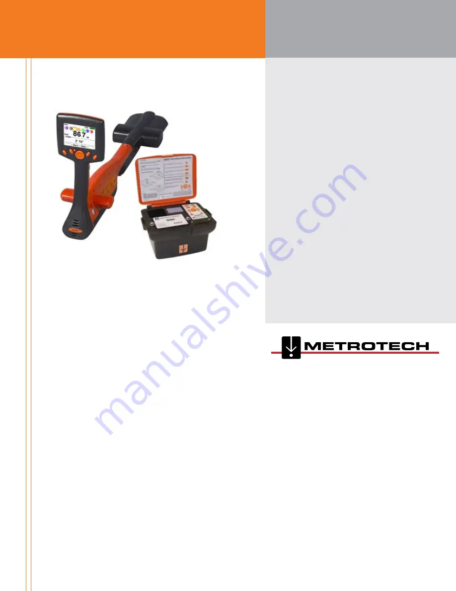
Metrotech MetroMark i5000 Series Скачать руководство пользователя страница 1

Metrotech Corporate  

Headquarters

3251 Olcott Street
Santa Clara, CA 95054
1 800 446 3392 Toll Free - Sales
1 800 638 7682 Toll Free - Service
1 408 734 1400 Direct
1 408 734 1415 Fax
[email protected]

www.metrotech.com

Metrotech Eastern

Service Center

5211 Linbar Drive, 
Suite 503
Nashville, TN 37211
1 800 624 6210 Toll Free
1 615 366 7323 Direct
1 615 360 9855 Fax
[email protected]

Metrotech Northeastern

Sales Center

89 South Commerce Way,
Suite 940
Bethlehem, PA 18017
1 866 644 8537 Toll Free
1 610 861 1996 Direct
1 610 861 1935 Fax

European Service Center 

SebaKMT

Dr.-Herbert-Iann-Str. 6
96148 Baunach, Germany
+ 49 9544 680 Direct
+ 49 9544 2273 Fax
[email protected]

www.sebakmt.com

Warranty: One year. Specifications subject to change without notice, ISO 9001: 2000 Certified. © 2008. All Rights Reserved 

Bluetooth

®

 is a registered trademark of Bluetooth SIG Incorporated.  


         Rev.B   9/17/08

CONTACT INFORMATION

OPERATIONS MANUAL

i5000


MetroMark

Содержание MetroMark i5000 Series

Страница 1: ...ille metrotech com Metrotech Northeastern Sales Center 89 South Commerce Way Suite 940 Bethlehem PA 18017 1 866 644 8537 Toll Free 1 610 861 1996 Direct 1 610 861 1935 Fax European Service Center SebaKMT Dr Herbert Iann Str 6 96148 Baunach Germany 49 9544 680 Direct 49 9544 2273 Fax service sebakmt com www sebakmt com Warranty One year Specifications subject to change without notice ISO 9001 2000 ...

Страница 2: ...ich has been altered or repaired by other than a Metrotech approved procedure been subject to misuse misapplication improper maintenance negligence or accident has had its serial number or any art thereof altered defaced or removed or been used with parts other than those approved by Metrotech Warranty does not include batteries Expendable items such as fuses and lamps are excluded Any detection p...

Страница 3: ...servicing disciplines Copyright Metrotech Corporation 2008 Metrotech Corporation 3251 Olcott Street Santa Clara CA 95054 USA Tel 1 800 446 3392 1 408 734 1400 Fax 1 408 734 1415 E mail sales metrotech com Internet www metrotech com The instrument meets the following standards EMC standard 89 336 EWG EEC Electromagnetic compatibility Changing modification rule 92 31 EWG As well as Low voltage regul...

Страница 4: ...ocate Mode 7 3 1 1 2 Operation Interface Marker Locate Mode 8 3 1 1 3 Display Elements 9 3 2 SideViews 10 3 3 Battery Pack 11 3 3 1 Recharging the Battery 11 4 Receiver Technical Specifications 12 4 1 Line Locate Mode 12 4 2 Electronic Marker System EMS Locate Mode 12 4 3 General System 12 4 4 Options 13 4 4 1 Standard Kit 13 4 4 2 Purchase Options 13 4 5 Accessories 13 5 Features 15 5 1 i5000 Met...

Страница 5: ...cessory Detection 23 5 7 Data Acquisition Optional 23 6 Menu System 24 6 1 i5000 MetroMark Menu System 24 6 2 Main Menu 24 6 2 1 Frequency Menu 25 6 2 1 1 Low Frequency 25 6 2 1 2 Mid Frequency 26 6 2 1 3 High Frequency 26 6 2 14 Power 27 6 2 1 5 RF 27 6 2 1 6 MarkerTypes 27 6 2 2 Mode Menu 28 6 2 2 1 Line Locate 29 6 2 2 2 Sonde Locate 29 6 2 2 3 Marker Locate 29 6 2 3 Settings Menu 29 6 2 3 1 Pe...

Страница 6: ...bal Mapping Software and an i5000 Optional 39 6 2 5 Shortcuts Menu 40 6 2 6 Data Logging Menu Optional 42 6 2 6 1Tickets 42 6 2 6 1 1 CreateTicket 43 6 2 6 1 2 ListTickets 43 6 2 6 1 3 Information 44 6 2 6 1 4 Activate 44 6 2 6 1 5 Clsoe 44 6 2 6 1 6 Enter Response 44 6 2 6 2 Data Log 45 6 2 6 2 1 Data Log Memory 45 6 2 6 2 2 Data Log Picture 45 6 2 6 3 Record Mode 46 6 2 6 4 Marker Read History 4...

Страница 7: ...i5000 MetroMark Manual vii 7 6Warranty 50 7 7 Copyright Notice 50 8 Notes 51 ...

Страница 8: ...7 i5000 SideView 10 3 8 Li ion Battery Pack 11 4 Receiver Technical Specifications 12 5 Features 15 5 1 Auto Gain Mode Interface 15 5 2 Manual Gain Mode Interface 15 5 3 Peak Position Graphical Bar Display 16 5 4 Left Right Guidance 16 5 5 Left Right Guidance 16 5 6 Signal Select Sample Scenario 18 5 7 Distortion Alert Sample Scenario 18 5 8 Recording Depth Measurement Interface 19 5 9 Depth Measu...

Страница 9: ...Personalize Selection Screen in Settings Menu 30 6 15 Audio Selection in Settings Menu 31 6 16 Initial Settings Selection in Settings Menu 32 6 17 Language Selection Mode 32 6 18Tools Settings Menu 32 6 19 Display Clock Selection inTools Settings Menu 33 6 20 GPS Clock Display inTools Settings Menu 33 6 21Time Zone Selection inTools Settings Menu 33 6 22 Daylight Savings Screen Setup inTools Setti...

Страница 10: ...1 6 42 GPS Status Screen in Shortcut Menu 42 6 43 Data Logging Selection in Main Menu 42 6 44Tickets Selection in Data Logging Menu 43 6 45 CreateTicket Selection in Data Logging Menu 43 6 46 ListTicket Selection in Data Logging Menu 43 6 47Ticket Information inTickets Menu 44 6 48 Sample Response Code Menu 44 6 49 Log Memory Selection in Data Log Menu 44 6 50 Data Log Memory in Data Logging Menu ...

Страница 11: ...oderate injury or material damage NOTE Notes have important information and useful tips on the operation of your equipment Nonobservance may result in incorrect measurement results Operating personnel Metrotech utility line and marker locators are intended for use by utility and contractor professionals Safety hazards for underground utility access areas include electrical shock explosive gases an...

Страница 12: ...ed for technical support and or service The instrument may only be operated when the malfunction is resolved FIVE SAFETY RULES The five safety rules must always be followed when working with High Voltage HV De energize Protect against re energizing Confirm absence of voltage Ground and short circuit Cover up or bar off neighboring energized parts Fire fighting in electrical installations Recommend...

Страница 13: ...isplay then reverts to the main locating screen The receiver is ready to perform locates Freq Gain Menu Vol 458 491Hz Man 42 82 8 dB Figure 2 2 Line Locate Operational Interface in Manual Gain Mode 2 Quick Start Guide Power ON Button Firmware releases version g Volume Level in Use h Volume Level in Use i Forward Looking Guidance Coil j Distortion Alert l 000 999 Signal Strength k Detected Signal S...

Страница 14: ...ormation about the locate The direction of the signal is indicated by the orientation of the orange arrow inside the guidance compass indicator A FORWARD pointing arrow indicates that the receiver detects a signal flowing away from the transmitter A DOWNWARD pointing arrow means that the signal is a return signal flowing back towards the transmitter Changes in the direction of the line relative to...

Страница 15: ...rational interface 7 Press the Type softkey to choose the desired electronic utility marker to be detected 8 Observe the signal strength to detect and determine the location of a buried marker The maximum signal strength will indicate the location of the buried marker 9 Press downward on the 4 way navigation to calculate marker depth Type Gain Menu LL 90 7 dB Gas Auto e Selected Marker Type to be ...

Страница 16: ... RF is always shown on the top left of the display Locate Mode Sonde In Sonde locate mode the active mode is displayed on the top left of the display Otherwise line locate mode is active Signal Gain Mode Auto Man Indicates Auto or Manual signal strength mode In auto mode sig nal strength is measured in decibels dB The auto gain mode can be readjusted pressing the 4 way navigation button up Manual ...

Страница 17: ...setup modes A separate Power ON button located near the navigation button provides easy access to activate power See figure below Top View Legend a GPS antenna optional b 4 way Navigation Button c Power ON Button d Operational Interface e Bluetooth Transmission ON Indicator f Soft Keys Figure 3 1 i5000 Top View 3 1 1 1 Operational Interface Line Locate Mode The i5000 MetroMark receiver operational...

Страница 18: ...The i5000 MetroMark receiver operational screen is a VGA bright color graphical display Three screens are displayed to the user marker locate mode measurement and marker read Figure 3 4 Marker Locate Interface Figure 3 5 Measurement Interface Figure 3 6 Marker Read Interface Active Marker Numerical field Signal Strength Estimated measured depth ...

Страница 19: ...ncy or the passive band name power or RF is always shown on the top left of the display Locate Mode Sonde In Sonde locate mode the active mode is displayed on the top left of the display Otherwise line locate mode is active Signal Gain Mode Auto Man Indicates Auto or Manual signal strength mode In auto mode sig nal strength is measured in decibels dB The auto gain mode can be readjusted pressing t...

Страница 20: ...ws The i5000 is equipped with a smart accessory connector and battery pack accessible from the receiver s right side panel Figure 3 7 i5000 Side View Side View Legend a GPS antenna optional b Smart Accessory Connector c Battery Pack Receptacle d IP67 RS232 serial connector port ...

Страница 21: ...ght cause other battery damage Excess heat can damage batteries causing a rupture or ignition Do not place batteries near fire heat or in direct sunlight The Li ion battery will charge in the i5000 receiver with the unit s power OFF No light indicator confirms the battery is charging Powering the unit ON will confirm the receiver battery is charging Attach the i5000 mains power supply to the charg...

Страница 22: ... m Marker Read Capability 10 digit ID number XXX XXX XXXX 3M EMS Marker iD only Operating Frequencies Utility Industry Code Frequency kHz Power Red 169 8 Water Blue 145 7 Sanitary Green 121 6 Telephone Orange 101 4 Gas Yellow 83 0 Cable Television CATV Orange Black 77 0 Non Potable NP Water General Purpose Purple 66 35 4 2 Electronic Marker System EMS Locate Mode Controls On off four way navigatio...

Страница 23: ...ttery pack AC power adapter for rechargeable battery 12 VDC automobile charger kit Operations manual Hard carrying case 4 4 2 Purchasable Options GPS MyLocator online web service for data logging warehousing and analysis Soft carrying case 4 5 Accessories A list of available i5000 accessories is below Part Accessory Description Search Coil The Search Coil is a multifunctional mini antenna that con...

Страница 24: ...ion battery pack Receiver Battery Holder Alkaline 9 AA cell alkaline battery holder A Frame Standalone A frame for pinpointing sheath faults Conductive Attach ment Kit Conductive attachment kit includes conductive leads for direct connection ground rod and carrying case Ground Rod Earth ground rod Sondes Small large and flexi sondes available in different op erating frequencies 982Hz 9 8KHz 35KHz ...

Страница 25: ...erline and depth of the target should first concentrate on locating the peak signal strength Signal strength is a representation of the amount of current flowing in an underground conductor at a particu lar depth If the depth is known the signal strength can be used to determine the level of current flowing in the conductor The signal strength value is displayed both numerically and graphically in...

Страница 26: ...the peak signal first The vertical green bar represents the underground utility using the null an tenna When shown on the left to the centerline it indicates the target is also to the left The arrow points towards the left directing the user to step in this direction Figure 5 4 Left Right Guidance When the vertical bar is shown to the right of centerline it indicates the target is to the right The...

Страница 27: ...ns and currents of the utilities with respect to the target line When distor tion is present the normal assumptions about the field behaving as a cylindrical shell around the conductor can be in various degrees invalid Therefore centerline current and depth estimates made in such distorted fields may also be biased In the i5000 receiver Distortion Alert and Signal Select are used to define the deg...

Страница 28: ...s not significantly biased though the depth estimate is less accu rate Distortion creates phase anomalies in the signal which can be detected at the receiver and compared to a phase reference imparted at the transmitter This reference is set by Signal Select modulation for every active frequency imparted at the transmitter The transmitter must be in direct conductive connection mode and Signal Sel...

Страница 29: ...d current of the target line The receiver must be at rest and held in a vertical position with the tip on the ground At this position the audio output is silent indicating that the receiver is at the centerline Do not solely rely on centering at the null for accurate depth and current measurements The centerline should be marked using the peak blue signal level bar and maximum signal strength read...

Страница 30: ...n to be buried underground the i5000 MetroMark can be easily converted with a softkey func tion to transmit a signal pulse from the receiver down to the ground This signal pulse for a single utility activates the buried marker that in turn generates a magnetic field response detected by the receiver Each marker depending upon the utility type emits a specific frequency signal The frequency emitted...

Страница 31: ...er Mode M operation 5 2 1 Changing the Marker Type Continuously press the Type softkey until the desired icon is selected and bound in the box Figure 5 12 Marker Locate Mode Operational Interface 5 2 2 Measuring Depth Once located the marker depth can be calculated by pressing downward on the 4 way navigation button The depth can be recorded as a Marked position if desired by pressing the Mark sof...

Страница 32: ...by pressing the 4 way navigation button downward Figure 5 16 Sonde Locate Mode Operational Interface 5 4 Wireless Connection The i5000 is equipped with Bluetooth wireless transmission When active either incoming or outgoing a blue LED emits from the receiver s top right corner This can indicate that a Bluetooth camera phone a transmitter or a PC or other device host is currently connected and tran...

Страница 33: ...ly acquires calibration information from the accessory and thus allows the receiver to determine what type of accessory is present Metrotech accessories such as speaker or headphone audio output host serial cable search coils etc are avail able accessory options 5 7 Data Acquisition Optional Locate data is recorded and stored in the receiver s memory until uploaded to Metrotech s MyLocator website...

Страница 34: ... activates or deactivates any of the available receiver frequencies Depending on the con figuration of your i5000 MetroMark receiver the following frequencies may be available See the table below for the available frequencies Region Base Frequency Set Hz North America 491 982 8 44k 9 82k 35 4k 82k 83k 50 60 100 120 RF International 491 512 577 640 982 8k 8 44k 9 82k 35 4k 65 6k 82k 83k 50 60 100 1...

Страница 35: ...or use Selecting fewer frequencies allows faster toggling between frequencies from the operational interface Figure 6 3 Low Frequency Selection Screen in Frequency Menu 6 2 1 2 Mid Frequency Mid frequencies are in the range between 1kHz and 10kHz Use the 4 way navigation button to move up and down the frequency list Use the 4 way navigation button to move right to highlight the frequencies Press t...

Страница 36: ... for use Selecting fewer frequencies allows faster toggling between frequencies from the operational interface Figure 6 5 High Frequency Selection Screen in Frequency Menu 6 2 1 4 Power The Power menu allows selection between 50Hz 60Hz passive locating modes and their harmonics Use the 4 way navigation button to move up and down the frequency list Use the 4 way navigation button to move right to h...

Страница 37: ... 6 7 RF Selection Screen in Frequency Menu 6 2 1 6 Marker Types The marker frequency selection menu displays the marker types that can be located with the i5000 MetroMark The available markers are listed below Using the 4 way navigation button move up and down the menu list to highlight the desired frequency set Use the 4 way navigation button to move left and right to highlight the specific marke...

Страница 38: ...oftkey to open the desired menu screen Press Back to return to the operational interface Use the 4 way navigation button to select another menu Figure 6 9 Mode Menu Selection 6 2 2 1 Line Locate Line Locate mode is used to trace the cable using a rack mount transmitter signal or a portable transmitter signal To access the line locate mode use the 4 way navigation button to select the desired mode ...

Страница 39: ...etect a specific frequency designated for a buried utility marker A depth calculation can be generated after locating the marker s peak signal To access the marker locate mode use the 4 way navigation button to select the desired mode Press the Select softkey to select the desired mode The receiver will automatically return to chosen opera tional interface Figure 6 12 Marker Locate Selection Scree...

Страница 40: ... Press Back to return to the previous menu Access the settings menu to reactivate them Figure 6 14 Personalize Selection Screen in Settings Menu 6 2 3 2 Audio The Audio menu controls the i5000 MetroMark receiver audio output characteristics Use the 4 way navigation button to move up and down the settings list Use the 4 way navigation button to move right and highlight the audio options Press the S...

Страница 41: ...gation button to move right and highlight the Initial Setup option Use the 4 way navigation button to move right and highlight the setup options The Backlight has three selectable options 60 seconds ON prior to turning OFF always ON or always OFF If the 60s option is selected any key push returns the backlight on for 60s should it have been timed out Press the Select softkey to toggle through the ...

Страница 42: ... the Back softkey to return to the previous inter face Figure 6 17 Language Selection Menu 6 2 3 3 2 Mapping Optional If the i5000 is enabled to pair with a GPS receiver the Mapping feature is configured to On Press the Select softkey to turn the feature off 6 2 3 4 Tools The tools settings menu can be used to set up the local time reference If GPS is enabled the default clock time will reflect GP...

Страница 43: ...revious screen Figure 6 20 GPS Clock Display in Tools Settings Menu 6 2 3 4 2 Time Zone The time zone can be manually selected according to the desired location Use the 4 way navigation to move upward or downward to highlight the desired location Press the Select softkey to change the time zone Figure 6 21 Time Zone Selection in Tools Settings Menu 6 2 3 4 3 Daylight Savings The clock time can be ...

Страница 44: ...o lock onto the satellite position Fix number of satellites locked onto the current position Sats and expected horizontal position error EHPE 6 2 3 6 Preset State The Preset State menu option allows the operator to restore the i5000 MetroMark receiver user interface configu ration to factory default settings for all menu selections in just one simple operation Selecting the Preset State function d...

Страница 45: ... softkey to return to the factory default settings 6 2 3 7 About The About screen displays important information about the i5000 MetroMark receiver s software and hardware configuration Use the 4 way navigation button to move up and down the settings list Press the Select softkey to choose the About option Press the Back softkey to return to the previous interface Figure 6 26 About Selection in Se...

Страница 46: ...enu screen Press Back to return to the operational interface Use the 4 way navigation button to select another menu Figure 6 28 Bluetooth Selection in Main Menu 6 2 4 1 Discoverable To open a connection with other Bluetooth enabled devices the receiver must be set to Discoverable This places the i5000 MetroMark receiver open to connections with other Bluetooth devices for 60 seconds During this pe...

Страница 47: ...luetooth device may be used Follow the supplier s instructions to properly install the Bluetooth driver prior to attempting any i5000 communication If your PC or device requires a passkey to complete a pairing a default passkey code of 0000 can be used Sending voice recordings or images from a Bluetooth enabled camera personal digital assistant PDA or cam era phone typically requires a simpler app...

Страница 48: ...d receiver are in close proximity I e within one foot pairing may become difficult Separate the two units with greater distance and retry Figure 6 32 Search Feature in Paired Devices Menu Upon completion of the transmitter discovery the receiver displays the paired transmitter The last four digits of each transmitter denotes the unique identity of each paired unit To remove a paired transmitter us...

Страница 49: ...Mapping feature at the fac tory or through MyLocator to properly pair a receiver and a mobile GPS receiver To pair a mobile GPS receiver and i5000 use the 4 way navigation button to select the Global Mapping feature in the Bluetooth Settings menu Figure 6 34 Global Mapping Screen in Bluetooth Settings Menu Following the same instructions above for pairing a transmitter and receiver press Select to...

Страница 50: ...creen Press Back to return to the operational interface Use the 4 way navigation button to select another menu Figure 6 36 Shortcuts Selection in Main Menu Use the 4 way navigation button to move up and down the Shortcuts list Press the Select softkey to activate or deactivate the options Press the Back softkey to return to the previous interface Selecting Adjust Volume places the shortcut to Adju...

Страница 51: ...ker mode during normal use Press the LL shortcut softkey to switch to line locate mode Press the M shortcut softkey to switch to marker locate mode Figure 6 40 Line Locate Marker Switch Shortcut Menu Screen The Smart Marker Read will only function as described if used on an i5000 MetroMark receiver Selecting the Smart Marker Read Read shortcut softkey allows the user to initiate the RFID marker re...

Страница 52: ... and agreeing to the service contract terms Three selections are available in this menu Tickets Data Log Record Mode To access the data logging menu use the 4 way navigation button to highlight the file folder icon The chosen menu is also labeled Data Logging at the top of the menu screen Press the Select softkey to open the desired menu screen Press the Back softkey to return to the operational i...

Страница 53: ...ts can be renamed once in MyLocator to better distinguish the data information from other locates Press the Select softkey to create a new ticket on the receiver Figure 6 45 Create Ticket Selection in Data Logging Menu 6 2 6 1 2 List Tickets All the tickets in memory will be listed along with the menu option Information Activate Close Enter Response To view a list of all tickets created use the 4 ...

Страница 54: ...evious interface All depth and mark measurements taken thereafter will be associated with the open ticket 6 2 6 1 5 Close Selecting Close deactivates a ticket and no data will be logged under that ticket The ticket name will be stricken through denoting its closure Closing a ticket automatically launches the response code selection menu 6 2 6 1 6 Enter Response Selecting Enter Response opens the r...

Страница 55: ... 6 2 2 Data Log Pictures Selecting Pictures displays the name and size of all Locate Images in memory Images are recorded in chrono logical order No viewing capability is currently available on the receiver LCD Images can be uploaded however to the MyLocator web service and viewed Press the Back softkey to return to the previous interface To log a picture into the receiver memory a Bluetooth ready...

Страница 56: ...d Figure 6 52 Record Mode in Data Logging Menu 6 2 6 4 Marker Read History The marker read history provides a data log of RFID recorded serial numbers Figure 6 53 Marker Read History in Data Logging Menu The collected data include the date marker type and serial number of each marker that is successfully read The data log information will be stored in the receiver s memory until the unit is synchr...

Страница 57: ...ew section 2 4 3 for instructions to pair Bluetooth devices To link the PC and i5000 receiver with a female female 9 pin RS232 serial null modem cable a special Me trotech RS232 adapter cable must be used If a male 9 pin serial connector port is not available on your PC or laptop a USB to male 9 pin serial connector adapter may be used After logging into MyLocator select the Synchronization menu t...

Страница 58: ... instrument can demonstrate potential problems such as centerline variations depth reading errors and signal strength fluctuations Use of the Verification Site does not substitute for routine and periodic calibrations But if used regularly it can point out to the operator any variations in readings that the unit typically has at the Verification Site 7 3 Troubleshooting Guide On occasion the equip...

Страница 59: ...0 instrument The following parts are available for replacement and repair purposes if necessary RECEIVER PART NUMBER Right Main Housing R11125 Left Main Housing R11134 Make Break Seal R11049 Display Rear Cover R11132 Inner Battery Gasket R11230 Outer Battery Gasket R11059 Keypad R10991 10 pin Cable Strip R162771 20 pin Cable Strip R162773 GPS Cable R11319 Bottom Antenna Housing R11102 PN Top Anten...

Страница 60: ...ure been subject to misuse misapplication improper maintenance negligence or accident has had its serial number or any part thereof altered defaced or removed or been used with parts other than those approved by Metrotech Warranty does not include batteries Expendable items such as fuses and lamps are excluded Any detection product proved defective under this warranty will be repaired or replaced ...

Страница 61: ...Metrotech Corp 51 Metrotech Copyright 2008 Doc No R12015 8 Notes ...

Страница 62: ... Metrotech Corporation 3251 Olcott Street Santa Clara CA 95054 USA www metrotech com i5000 TM MetroMark TM ...

Отзывы: