DSP Implementation Guide
244
To the left are the inputs for the graph, and to the right are the outputs. A newly instantiated graph has the
inputs and outputs connected, so that it will not interrupt the signal. The I/O will match the number of channels
in the object the graph is inserted in; a mono channel will have a mono graph, a stereo channel will have
two channels of audio in the graph, etc.
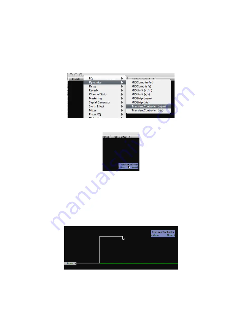
The Plug-in pop-up menu contains all of the available instantiable plug-ins. When you select a plug-in from
this menu, a new instance is created on the selected DSP, and you may drag the instance to a convenient
location in the Graph area.
Figure 15.8: Selecting a New Instance from the Plug-in Menu
Figure 15.9: Positioning the New Instance in the Graph
Once you have added the Plug-ins you want to use, you can wire them up. To make connections, click on a
port (one of the small gray triangles next to the port name), and then drag the connection to the target. When
you have made a valid connection, the connection line will switch from Gray to Green. You can make as
many mults as you like of a signal source but only one connection can be made to a processor input or process
bus port. If you make a new connection to an input that already has a connection, the old connection will
be automatically disconnected. To remove a connection without establishing a new one,
⌃
(Control)-click on
the input port to which the connection is made.
Figure 15.10: Starting a Connection
Содержание +DSP
Страница 1: ...Mo b i l e I O U s e r s G u i d e...
Страница 17: ...Mobile I O Users Guide 17 321 Phase Cancellation 362...
Страница 21: ...Part I Quick Start Guides...
Страница 53: ...Part II Interfaces...
Страница 127: ...Part III Software...
Страница 132: ...Software 132 Band Split 314...
Страница 229: ...Routing Examples 229 Figure 13 45 Output Tab Create 16 mono outputs and map them to DAW 1 16 in MIO Console...
Страница 315: ...Part IV Appendices...
Страница 317: ...Appendices 317 J Support Resources 351 K Changelog 352...


