Mendota MEDALLION Скачать руководство пользователя страница 5

LOCATING THE STOVE 

SAFETY AND STRUCTURAL CONCERNS: 
 The Mendota Direct Vent Freestanding Stove 

must be installed and serviced by a qualified Mendota approved service 

person.  The Mendota Direct Vent Freestanding Stove

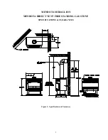
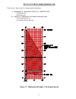
 may be placed within 2" of a rear wall, within 10" of side walls, 

within 1 1/2" of corner walls and 39" below an alcove ceiling [See Figure 2:  Specifications & Clearances on page 
5].  The Stove can be installed on any rigid floor construction.  A metal or wood floor protector extending the full 
width and depth of the Stove MUST be used when the Stove is installed on carpet, vinyl or any combustible surface 
other than wood flooring. 

The stove is equipped with a safety control system designed to protect against improper venting of combustion 
products. 
 
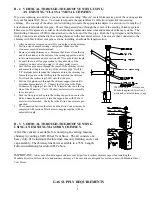
VENTING REQUIREMENTS: 

Use only approved direct venting kits when installing your stove.  Closely follow venting directions and 
requirements (see 

FLUE VENTING INSTRUCTIONS

 starting on page 8).  Observe the restriction relating to vent 

position on exterior of home (see 

Exterior Vent Locations

 on page 7). 

HEATING PERFORMANCE: 

The Mendota Direct Vent Freestanding Stove is a true, high efficiency gas heater.  With its heat input of 40,000 
(35,000 L.P.) BTUH the Mendota Stove will heat a large area of your home if situated to maximize heat circulation.  

NOTE:

  The Stove is a major source of supplemental heat.  

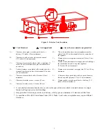
Air movement options for maximizing heat circulation which can be considered are through-the-wall grills or floor 
grills, or the continuous operation of central heating blowers or ceiling fans. 

The most efficient and successful method for overall heat distribution is a ceiling fan - we recommend this method for the owner 
who wishes to maximize hot air distribution and efficient utilization of heat. 

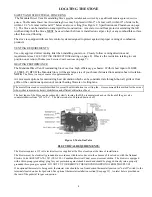
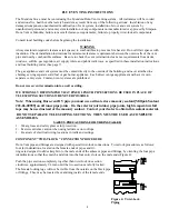
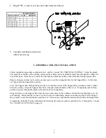
The heat input of the Stove can be reduced by slowly turning the Hi/Lo temperature knob on the front of the gas valve 
counterclockwise from "Hi" to "Lo".  The blower can also be turned down or off. 


Figure 1: Main Gas Valve


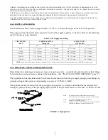
ELECTRICAL REQUIREMENTS: 

The blower requires a 115 volt electrical service supplied at the Stove location at the time of installation. 

The blower must be electrically grounded in accordance with local codes or in the absence of local codes, with the National 
Electric Code ANSI/NFPA 70-1987 (CSA C22.1-Canadian Electrical Code) or most current edition.  The blower is equipped 
with a three-prong (grounding) plug for your protection against shock hazard and should be plugged directly into a properly 
grounded three-prong receptacle.  DO NOT CUT OR REMOVE THE GROUNDING PRONG FROM THIS PLUG! 

If an optional thermostat is being used, thermostat wire should be run from desired thermostat location (or "on/off" switch) to the 
terminals located on back of pedestal--See optional thermostat installation section [See page 22].  An inlet hole is provided on 
the rear of the pedestal for gas connection. 


4

Содержание MEDALLION

Страница 1: ...TINGUISH ANY OPEN FLAME 5 IMMEDIATELY CALL YOUR GAS SUPPLIER FROM A NEIGHBOR S PHONE 6 FOLLOW THE GAS SUPPLIERS INSTRUCTIONS 7 IF GAS SUPPLIER IS UNAVAILABLE CALL YOUR FIRE DEPARTMENT DO NOT STORE OR...

Страница 2: ...AL TOTAL WEIGHT 225 LB SAFETY AGA CERTIFIED PILOT GENERATOR MILLIVOLT THERMOCOUPLE SYSTEM ACTIVATED WITH SWITCH OR THERMOSTAT GAS REQUIREMENTS SUPPLY PRESSURE NAT GAS 7 W C 5 W C MIN 11 W C MAX L P GA...

Страница 3: ...on repair and any adjustments to logs or burner must be done by a qualified service person The Stove should be inspected before use and at least annually by a professional service person More frequent...

Страница 4: ...ant Si aucun code n existe suivez la norme ANSI Z223 1 ou la norme CAN CGA ACNOR B149 _______________________________________________ MINIMUM CLEARANCES FROM COMBUSTIBLE CONSTRUCTION Unit to sidewall...

Страница 5: ...urce of supplemental heat Air movement options for maximizing heat circulation which can be considered are through the wall grills or floor grills or the continuous operation of central heating blower...

Страница 6: ...MENDOTA MEDALLION MENDOTA DIRECT VENT FREESTANDING GAS STOVE SPECIFICATIONS CLEARANCES Figure 2 Specifications Clearances 5...

Страница 7: ...ss window door by releasing the 4 turn latches behind side doors rotate latches counterclock wise and pull outward and carefully sliding glass door forward 4 You are now ready to hook up the gas suppl...

Страница 8: ...Vertical clearance to ventilated soffit located above the terminal from the center line of the terminal 18 inches 46 cm minimum K Clearance to a mechanical air supply inlet 6 feet 1 8 m minimum E Cle...

Страница 9: ...rate vent system Common vent systems are prohibited Do not recess vent termination into a wall or siding WE STRONGLY RECOMMEND THAT FIXED LENGTH PIPE SECTIONS BE USED IN PLACE OF TELESCOPING SECTIONS...

Страница 10: ...Galvanized 36 RIGID VENT STACK PIPE Black 48 RIGID VENT STACK PIPE Galvanized 48 RIGID VENT STACK PIPE Black 11 14 5 8 ADJUSTABLE VENT PIPE Black Only 2 90 ELBOW Galvanized 90 ELBOW Black 3 45 ELBOW G...

Страница 11: ...ypes of venting system installations A HORIZONTAL THROUGH THE WALL TERMINATION 1 Minimum rise 2 Elevated rise B VERTICAL THROUGH THE ROOF TERMINATION 1 Through typical roof 2 Through existing chimney...

Страница 12: ...pendicular to the wall The height of the opening must be located to meet all local and national building codes and not allow the termination to be easily blocked or obstructed If wall being penetrated...

Страница 13: ...system is attached If this is the case you may want to adjust the stove location 2 Locate position where vent pipe will pass through any ceilings and will penetrate the outside wall Since vent pipe s...

Страница 14: ...rilled hole placed in the roof in No 1 The opening should be a sufficient size to meet all clearance requirements Continue to assemble lengths of pipe and elbows necessary to reach the Ceiling Support...

Страница 15: ...tangular hole for the Support Box Cut the hole 1 8 larger than the Support Box outline Lower the Support Box through the hole in the roof until the bottom of the Support Box protrudes at least 2 inche...

Страница 16: ...through the center of the chimney system and center the Adapter on the top of the chimney pipe Drill 4 1 8 diameter holes through the Adapter and into the chimney top Insure that you are in fact drill...

Страница 17: ...2 1 3cm 5 8 1 6cm 1 2 1 3cm 40 100 1 2 1 3cm 1 2 1 3cm 3 4 2 0cm 1 2 1 3cm 100 150 3 4 2 0cm 1 2 1 3cm 7 8 2 3cm 5 8 1 6cm 150 200 3 4 2 0cm 1 2 1 3cm 7 8 2 3cm 3 4 2 0cm NOTE Some areas allow copper...

Страница 18: ...r s capacity is not sufficient to add the Gas Stove an additional inches to inches regulator must be installed for the Stove EXCEPTION Some codes allow 2 PSI 1 4KPA supplies to enter the residence in...

Страница 19: ...t be installed in accordance with instructions and local and national codes LIGHTING CHECK OFF LIST All items on Installation Check Off List see above must be completed If thermostat or remote control...

Страница 20: ...s in place cycle the burner again to make sure of prompt ignition of burner that flame runs smoothly around burner and does not lift off burner NOTE Flames may not come through coals until glass is in...

Страница 21: ...Log Fire View Figure 9 Log Module 2 0...

Страница 22: ...Carefully unpack one piece log assembly and center on log rest between Side Log Tabs Place log assembly over front locating pins 5 Place glowing embers wool sparsely on top coals in front of front lo...

Страница 23: ...ER DOES NOT COME ON IMMEDIATELY AFTER SECOND TRY RECHECK COMPLETE INSTALLATION OF LOGS PILOT ETC TO INSURE PROPER PILOT FLAME IMPINGEMENT ON THE THERMOPILE AND PROMPT BURNER IGNITION NEVER TURN BURNER...

Страница 24: ...in gas pressure B Carbon dirt or lint Have your gas supplier check for correct gas 7 W C Nat Gas 11 W C LP Gas If flame still needs adjustment see Flame Adjustment below Clean out carbon spider webs...

Страница 25: ...ves that are put in gas both natural and propane to make it smell can be harmful to glass and can leave a white film deposit on the glass This deposit can be removed with cleaners such as KEL KEM Poli...

Страница 26: ...side 7 18 50 01 00017 Pop Rivet 1 8 x 1 4 Aluminum WARNING Use only authorized parts and materials obtained from Johnson Gas Appliance when replacing defective or damaged glass DO NOT substitute other...

Страница 27: ...illivolt generation and assure trouble free burner operation Readings must be taken with a Pilot ONLY operating b Main Burner operating A PILOT ONLY OPERATING Thermostat OFF Minimum Millivolts 325 Usi...

Страница 28: ...e pg 20 for location Orifice is removed and installed with a deep well socket and ratchet 2 Install pilot orifice 05 04 00036 014 see pg 28 for location Remove and install pilot hood with 7 16 open en...

Страница 29: ...K 45 01 00101 908B STACK 6 RIGID VENT BLACK 45 01 00098 911B 11 14 ADJUSTABLE PIPE 45 01 00148 917B ADJUSTABLE PIPE 17 24 BLACK 45 01 00143 945BG ELBOW 45 DEG SWIVEL BLACK 45 01 00142 945G ELBOW 45 DE...

Страница 30: ...Piezo Igniter 65 14 00050 Main Orifice L P Gas 50 35 01 00239 Ember Wool 65 06 00435 Metallic Black Paint Spray Can 05 07 00061 Thermopile 50 06 00065 Door Latch 05 07 00067 Thermocouple 50 06 00064...

Страница 31: ...urer s specifications INSTALL PROPER SIZE GAS LINES CHECK FOR GAS LEAKS Per Manual CHECK FOR CORRECT GAS PRESSURE AT MANIFOLD Per Manual a 3 5 Inches Water Column Maximum Nat Gas b 10 5 Inches Water C...

Страница 32: ...TAPE SHUT POSTAGE NEEDED JOHNSON GAS APPLIANCE COMPANY 520 E AVENUE N W CEDAR RAPIDS IA 52405 3 1...

Страница 33: ...NOTES NOTES 3 2...

Страница 34: ...MENDOTA EXTENDED LIFETIME PROTECTION AND LIMITED WARRANTY MENDOTA MEDALLION SDV40 DIRECT VENT GAS STOVE 3 3...

Страница 35: ...warranted against burn out Mendota has the right to investigate and inspect the exact original stove and entire installation without any alterations or tampering in the event a claim is made to determ...

Страница 36: ...Johnson Gas Appliance Company 520 E Avenue N W Cedar Rapids IA 52405 WEBSITE www johnsongas com 0405 Part 85 03 00701...

Отзывы: