DMU380ZA Series
User’s Manual
________________________________________________________________________
Doc# 7430-3810 Rev.02
Page 9
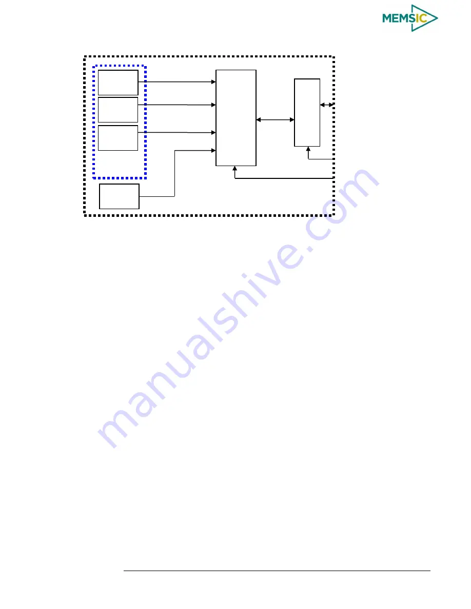
Figure 3 DMU380ZA Series Hardware Block Diagram
Figure 4 shows the software block diagram. The 6-DOF inertial sen sor cluster data is
fed into a high speed 200Hz signal processing chain. These 6-DOF signals pass through
one or more of the processing blocks and these signals are converted into output
measurement data as shown. Measurement data packets are available at fixed continuous
output rates or on a polled basis. The type of measurement data packets available depends
on the unit type according to the software block diagram and Table 5. Aiding sensor data
is used by an Extended Kalman Filter (EKF) for drift correction in the INS, AHRS and
VG Series products. Built-In-Test and Status data is available in the measurement packet
or via the special Status Packet T0.
As shown in the software block diagram, the DMU380ZA Series has a unit setting and
profile block which configures the algorithm to user and application specific needs. This
feature is one of the more powerful features in the DMU380ZA Series architecture as it
allows the DMU380ZA Series to work in a wide range of commercial applications by
settings different modes of operation for the DMU380ZA Series.
6-DOF Sensor
Cluster
X / Y / Z
Gyros
X / Y / Z
Accelerometers
High-Speed
Sampling &
+
Sensor
Compensation /
Filtering
+
Navigation &
Attitude
Kalman Filter
UART1
SPI
UART2
System Digital Outputs and Inputs
UART1 (Pins 3,4) or SPI (Pins 3-6)
MEMSIC Serial Protocol (UART1)
SPI Registers (SPI)
X / Y / Z Acceleration
Roll / Pitch / Yaw Rate
X / Y / Z Magnetic Fields (INS/AHRS only)
Temperature
Sensor
X / Y / Z
Magnetometers
UART2 External GPS Input
(VG/AHRS/INS)
SPI Com Sync 1 KHz Pulse
External GPS 1 PPS Input
Pin 2


