SECTION 5
MAINTENANCE
143
Replacing the Printhead Cartridge
The following procedure describes how to remove the Printhead Cartridge from the printer.
NOTE:
We recommend the use of nitrile powder-free gloves for this process.
1.
Plug in the printer. Turn the printer’s Main Power Switch ON; then press the control panel’s
ON/OFF button. Wait about 45 seconds for the print engine to power-up (ON/OFF button will
illuminate).
2.
Open the Top Cover.
3.
Open the Toolbox utility.
4.
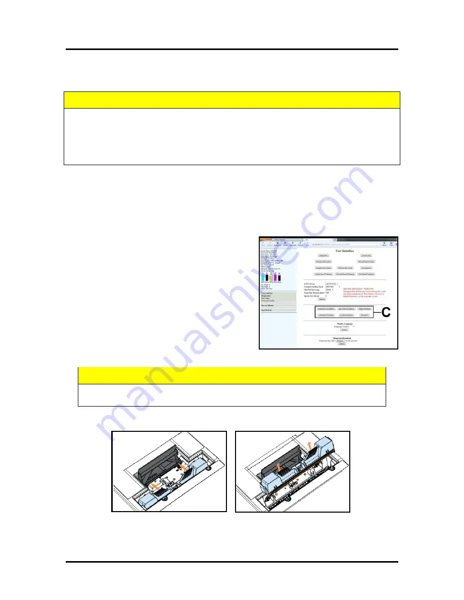
Click on the button labeled “Release Printhead”;
located in the Advanced Buttons area [C] of the
User Interface screen.
The printer will run a partial deprime routine and
then the printhead latch will release so it can be
opened.
WARNING!
If the printhead latch fails to release
do not force the latch open. Severe damage will
result. Contact technical support.
5.
Open the Printhead Latch fully to disengage the ink couplings from the printhead cartridge.
6.
Remove the old printhead as shown below. Tilt the cartridge back and then lift up to remove.
7.
To help reduce ink spills; place the printhead into the old protective packaging and discard.
8.
Once the old Printhead Cartridge has been removed; please refer to the section titled “Installing
the Printhead Cartridge”; to install the new Printhead Cartridge.
ATTENTION
If you experienced fuzzy print quality or an abrupt failure in a particular area of nozzles on
the previous printhead; we recommend that you have the service station
inspected/cleaned and the wiper roller replaced, before installing the new printhead. If not;
the chance of damage to the new printhead is greatly increased.
Service station maintenance and wiper roller replacement should only be performed by a
qualified/trained person.
WARNING
Never attempt to open the Printhead Latch manually, when in the closed/locked position.
Severe damage will result. Use the Release Printhead button from the Toolbox Utility.
Содержание AS-1180C
Страница 1: ...MACH 8 HJ AS 1180C HIGH CAPACITY DIGITAL COLOR PRINTER SERVICE MANUAL Rev 05 27 14 PRELIMINARY ...
Страница 75: ...SECTION 4 DISASSEMBLY AND ASSEMBLY 73 a J1002 Cable J1002 Socket Location Connection ...
Страница 76: ...SECTION 4 DISASSEMBLY AND ASSEMBLY 74 b J1000 Cable J1000 Socket Location Connection ...
Страница 77: ...SECTION 4 DISASSEMBLY AND ASSEMBLY 75 c J551 Cable J551 Socket Location Connection ...
Страница 78: ...SECTION 4 DISASSEMBLY AND ASSEMBLY 76 d J703 Cable J703 Socket Location Connection ...
Страница 79: ...SECTION 4 DISASSEMBLY AND ASSEMBLY 77 e P2002 Cable P2002 Socket Location Connection ...
Страница 80: ...SECTION 4 DISASSEMBLY AND ASSEMBLY 78 f P2004 Cable P2004 Socket Location Connection ...
Страница 81: ...SECTION 4 DISASSEMBLY AND ASSEMBLY 79 g P2006 Cable P2006 Socket Location Connection ...
Страница 82: ...SECTION 4 DISASSEMBLY AND ASSEMBLY 80 h J35 Cable J35 Socket Location Connection ...
Страница 83: ...SECTION 4 DISASSEMBLY AND ASSEMBLY 81 i P1 Cable P1 Socket Location Connection ...
Страница 84: ...SECTION 4 DISASSEMBLY AND ASSEMBLY 82 j P2005 Cable P2005 Socket Location Connection ...
Страница 85: ...SECTION 4 DISASSEMBLY AND ASSEMBLY 83 k P2003 Cable P2003 Socket Location Connection ...
Страница 86: ...SECTION 4 DISASSEMBLY AND ASSEMBLY 84 l J20 Cable J20 Socket Location Connection ...
Страница 87: ...SECTION 4 DISASSEMBLY AND ASSEMBLY 85 m J2001 Cable J2001 Socket Location Connection ...
Страница 180: ......
Страница 181: ...Copyright Neopost USA 2014 ...


