15
PN: 81127
Rev 4, 6/2017
Pressing the Configuration button
will allow the user to configure both the SPI hardware and SPI
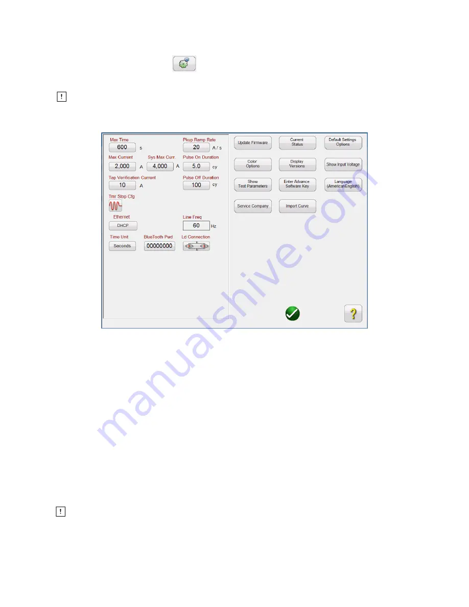
software. Pressing this button will display the Configuration screen (see Figure 9).
Note: The following button descriptions vary depending on hardware configuration and the
version of the SPI software. The STVI version of the software includes extra buttons as indicated
with an * in the descriptions below.
Figure 9
– SPI Configuration Screen
2.3.1.1
Max Time
The user can set the Maximum Time in seconds that the SPI will stay ON during a test. The default value
is 600 seconds.
2.3.1.2
Max Current
The user can set the Maximum Current that the SPI will output on the selected Output Tap. The default
value is 2000 Amps.
2.3.1.3
Tap Verification Current
This is a time saving feature used to automatically determine the Output Tap selected by the user. The
user simply connects to the desired output tap, and then to the device under test. Prior to applying a test
current the unit will pulse the Tap Verification Current into the load. Based upon the current value read
back by the measuring circuit, and knowing the ratio of the output taps, the software will automatically
reconfigure for the selected output tap. The default is 10 Amps.
Make sure that the Tap Verification Current value is below any instantaneous setting or
ground trip device setting of the device under test.
2.3.1.4
Timer Stop Cfg


