background image

Maximum Current Output a.c.

PCITS2000/2

2000 A at 0 to 3 V, 50 Hz/60 Hz
1000 A at 0 to 6 V, 50 Hz/60 Hz

PCITS600/2

600 A at 0 to 4 V, 50 Hz/60 Hz
300 A at 0 to 8 V, 50 Hz/60 Hz

Auxiliary Voltage Output a.c.

0 to 250 V, 0-2 A, 50 Hz/60 Hz
0 to 125 V, 0-2 A, 50 Hz/60 Hz
All outputs are able to rise to 50 V above earth potential.

Timer Stop Inputs

Inputs for volt-free or a.c./d.c. energised contacts at
100 V to 264 V

Display

Dot matrix l.c.d.

Current Range PClTS 2000/2

0-2000 A, range resolution 1 A

Current Range PCITS 600/2

0-600 A, range resolution 1 A

Auxiliary Voltage Range

0-250 V, resolution 1 V; 0-2 A, resolution 0,01 A

Accuracy

±3% of reading ±2% LS digits

Elapsed Time

0-600 s, resolution 0,01 s, accuracy 0,1% ±0,05s

Duty Cycle

2

1

2

minutes on circuit and 15 minutes off circuit at full

range current and voltage. Duty cycle increases until
continuous use is possible at 40% of full range.

Temperature Range

Operation

0˚C to 40˚C

Storage

-20˚C to + 60˚C

Humidity Range

Operation

(900% RH at 40˚C for 48 hours)

Storage

(93% RH at 40˚C for 12 hours)

Supply Voltage

220 V/240 V +6%-10%, 50 Hz/60 Hz, single phase i.e.
198 V to 254 V at full output current.
7 kVA for PCITS2000/2, 3,5 kVA for PCITS600/2

Equipment Protection

Circuit Breakers

2 x 30 A rating breakers for PCITS2000/2, one short
delay and one long delay.
2 x 15 A rating breakers for PCITS600/2, one short delay
and one long delay.

Auxiliary Output Fuse

2 A ceramic HBC 20 mm x 5 mm IEC 127/1

Controller Supply Fuse

1 A ceramic HBC 20 mm x 5 mm IEC 127/1

Safety

The test set will, in general, meet the requirements of the
IEC 61010-1 specification

EMC

IEC 61326-1

Operational uncertainties

Refer to www.megger.com

Dimensions

PCITS2000/2

320 mm x 305 mm x 510 mm (12

1

2

in x 12 in x 20 in

approx.) excluding handles and wheels.

PCITS600/2

495 mm x 307 mm x 310 mm (19

1

2

) in x 12 in x 12

1

4

in

approx.) excluding handles.

Controller

202 mm x 127 mm x 55 mm (8 in x 5 in x 2

1

8

in approx.)

Weight

PCITS2000/2

61 kg (134 lb approx.)

PCITS600/2

38 kg (83

1

2

lb approx.)

Cleaning

Wipe disconnected, cooled Test Set with a clean cloth
damped with soapy water or Isopropyl Alcohol (I.P.A.)

Specification

8


Содержание PCITS2000/2

Страница 1: ...M PCITS600 2 PCITS2000 2 Primary Current Injection Test Sets User Guide Benutzerhandbuch...

Страница 2: ...ower is switched On The permitted duty cycle must not be exceeded Replacement fuses must be of the correct type and rating The main current terminals must not be connected to a live potential The Test...

Страница 3: ...city 19 Duration Tests 20 Circuit Description 21 Sicherheitshinweise 24 Betriebsanleitung 25 Repair and Warranty 36 Components List 37 Illustrations Figure 1 PCITS 600 2 and PCITS 2000 2 6 Figure 2 Pr...

Страница 4: ...l by which the test set may be separately earthed so that total reliance for earthing is not placed on the supply cable The supply cable must be terminated with a suitable plug bearing in mind the kVA...

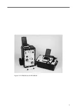
Страница 5: ...5 Figure 1 PCITS600 2 and PCITS2000 2...

Страница 6: ...n a bi metallic sensor is mounted in the main transformer which will operate if the duty cycle is exceeded and an adverse temperature rise in the test set results For safety the circuit has been desig...

Страница 7: ...ry testing usually requires a high current over 500 A Secondary current injection testing is easier since there is not the need to break the primary circuit and the current required through the operat...

Страница 8: ...Operation 900 RH at 40 C for 48 hours Storage 93 RH at 40 C for 12 hours SupplyVoltage 220 V 240 V 6 10 50 Hz 60 Hz single phase i e 198 V to 254 V at full output current 7 kVA for PCITS2000 2 3 5 kV...

Страница 9: ...ance lead set 3 m long 6220 462 600 A low inductance lead set 5 m long 6220 463 Duty cycle on test leads 21 2 minutes on and 15 minutes off Trolley for PCITS600 2 6320 224 Leads for timer stop and aux...

Страница 10: ...oltage is used and that the supply cable is terminated by a suitable plug The supply capacity must be sufficient to maintain the supply voltage within range at the full output of the test set 9 Use a...

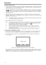
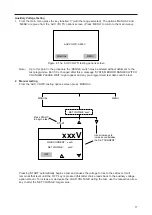
Страница 11: ...is Note This message occurs frequently during the testing procedure but remains only for a short time while the variac returns to zero and the circuit makes itself ready to continue When the test set...

Страница 12: ...extreme temperatures the display might need altering to obtain visibility The following procedure can be used for recovering normal display contrast a Using the POWER switch turn the test set off and...

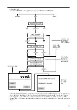
Страница 13: ...to the set level It will remain at that level until the OFF key is pressed this choice leads back to the current testing option screen To increase or decrease the test current during the test use the...

Страница 14: ...e option to REPEAT the test or ESCAPE to the current test sub menu figure 5 Operation 14 Return to the current testing option screen Use arrow keys to increase or decrease the SET CURRENT Output being...

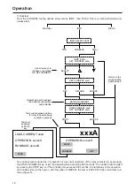
Страница 15: ...back time is then given with the option to REPEAT the test or ESCAPE to the current test sub menu figure 5 15 Return to the current testing option screen Use arrow keys to increase or decrease the SET...

Страница 16: ...ith the option to REPEAT the test or ESCAPE to the current test sub menu figure 5 Operation 16 Return to the current testing option screen Use arrow keys to increase or decrease the SET CURRENT Output...

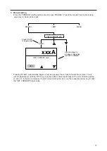
Страница 17: ...lost 2 Manual testing From the AUX VOLTS testing options screen press MANUAL Pressing START automatically begins a test and causes the voltage to rise to the set level It will remain at that level unt...

Страница 18: ...t ranges the warning is cleared if the test current is corrected in the allowed time However the indication remains for the duration of an IDMT test and the subsequent results screen This warns the op...

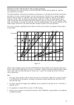
Страница 19: ...h less significant To give some guidance regarding the performance of various cross sections and lengths of cables figure 7a is provided With the leads strapped together the Foster PCITS2000 2 will de...

Страница 20: ...C ambient Recovery time after a full duration test is 15 minutes operation is continuous at approximately 40 of full power Operation 20 200 0 10 2 5 20 30 40 50 400 600 800 1 000 1 200 1 400 1 600 1 8...

Страница 21: ...ither series or parallel primary connections to change the output range of the test set It has an extra pole which is used to send a signal to the microprocessor so that the correct range can be indic...

Страница 22: ...ransformer combination A phased turn off prevents residual magnetization of the loading transformer and ensures proper re energisation These features significantly reduce nuisance effects caused by pr...

Страница 23: ...23...

Страница 24: ...r t nicht ber hrt werden Die zul ssige Betriebsdauer darf nicht berschritten werden Beim Austausch von Sicherungen mu die richtige Klasse und Sorte verwendet werden Die Netzstromanschl sse d rfen nich...

Страница 25: ...n Stecker versehen ist Die Netzstromkapazit t mu ausreichend sein um die Netzstromspannung innerhalb des Bereiches der vollen Leistung des Pr fger tes zu halten 9 Nur Netzsteckdosen mit Schutzerdung v...

Страница 26: ...erscheint beim Pr fen mehrmals f r kurze Zeit wenn sich der Variac auf Null stellt und der Stromkreis zum Fortsetzen der Pr fung vorbereitet wird Beim Einschalten des Pr fger tes vollzieht der Schrit...

Страница 27: ...ungen benutzt oder aufbewahrt wird m ssen die Bildschirmeinstellungen evtl ver ndert werden um ein Ablesen der Werte zu erm glichen Der normale Bildschirmkontrast l t sich wieder wie folgt einstellen...

Страница 28: ...ART wird die Pr fung automatisch begonnen und der Strom bis zum eingestellten Stand erh ht Dieser Stand wird beibehalten bis die Taste EIN gedr ckt wird womit zum Strompr fungs Optionsbildschirm zur c...

Страница 29: ...fung a Vorw rtspr fung W hlen Sie im Pr foptionsbildschirm STROM zun chst RELAIS und anschlie end VORL Die Betriebszeit wird auf dem Bildschirm dargestellt Die Pr fung wird unter einer der folgenden...

Страница 30: ...kte iii Dr cken der START R CKLAUF Taste oder iv nach 600 Sekunden mit laufendem Strom Der R cklaufzeitschalter wird durch Dr cken der STOP Taste angehalten oder stellt sich nach 600 Sekunden automati...

Страница 31: ...des Stroms ii Bet tigung der Relaiskontakte iii Dr cken der START R CKLAUF Taste oder iv nach 600 Sekunden mit laufendem Strom Der R cklaufzeitschalter wird durch Dr cken der STOP Taste angehalten ode...

Страница 32: ...NDERT BITTE WARTEN vorprogrammierte Pr fdaten sind dann m glicherweise verlorengegangen 2 Manuelle berpr fung Dr cken Sie im Pr foptionen Bildschirm HILFSSPANNUNG auf MANUEL Wenn Sie auf DR CKEN wird...

Страница 33: ...innerhalb der vorgegebenen Zeit korrigiert wird Bei einer IDMT Pr fung wird das Ausrufezeichen jedoch w hrend der Testdauer und auf dem folgenden Ergebnisbildschirm weiterhin angezeigt um den Bediener...

Страница 34: ...sultierende Induktanz spielt eine weitaus geringere Rolle In Abbildung 7a werden die Eigenschaften verschiedener Kabell ngen und querschnitte dargestellt Bei zusammengebundenen Kabeln liefert Foster P...

Страница 35: ...Pr fung bei einer bestimmten Ausgangsstromst rke und einer Umgebungstemperatur von 20 C dargestellt Die Erholungszeit nach einer vollen Testl nge betr gt 15 Minuten ein kontinuierlicher Betrieb ist be...

Страница 36: ...Archcliffe Road Valley Forge Corporation Center Dover 2621 Van Buren Avenuel Kent CT17 9EN Norristown PA 19403 England USA Tel 44 0 1304 502243 Tel 610 676 8579 Fax 44 0 1304 207342 Fax 610 676 8625...

Страница 37: ...37...

Страница 38: ...38...

Страница 39: ...APPES France T 33 1 30 16 08 90 F 33 1 34 61 23 77 OTHER TECHNICAL SALES OFFICES Toronto CANADA Sydney AUSTRALIA Madrid SPAIN Mumbai INDIA and the Kingdom of BAHRAIN Megger products are distributed in...

Отзывы: