Guidance in Choice of Test Leads for Current Carrying Capacity
The impedance of any lead set used to connect the Test Set to the load directly affects the maximum
current that can be achieved.
Given that impedance comprises both resistance and reactance, it is important that both these parameters
are kept to a minimum to allow the higher currents to be achieved. Therefore from a resistive viewpoint
leads of minimum length and maximum cross section will deliver the highest currents (eg Foster 2000 A
Lead Set, 3 m/190 mm2), and exhibit the least heating. However, it is often not realised that for leads
where the feed and return are placed far apart the inductive reactance is a maximum and of similar ohmic
value to the resistance, whereas if the feed and return are strapped together, the inductive fields around the
cables largely cancel and the associated inductive reactance becomes much less significant.
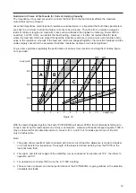
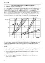
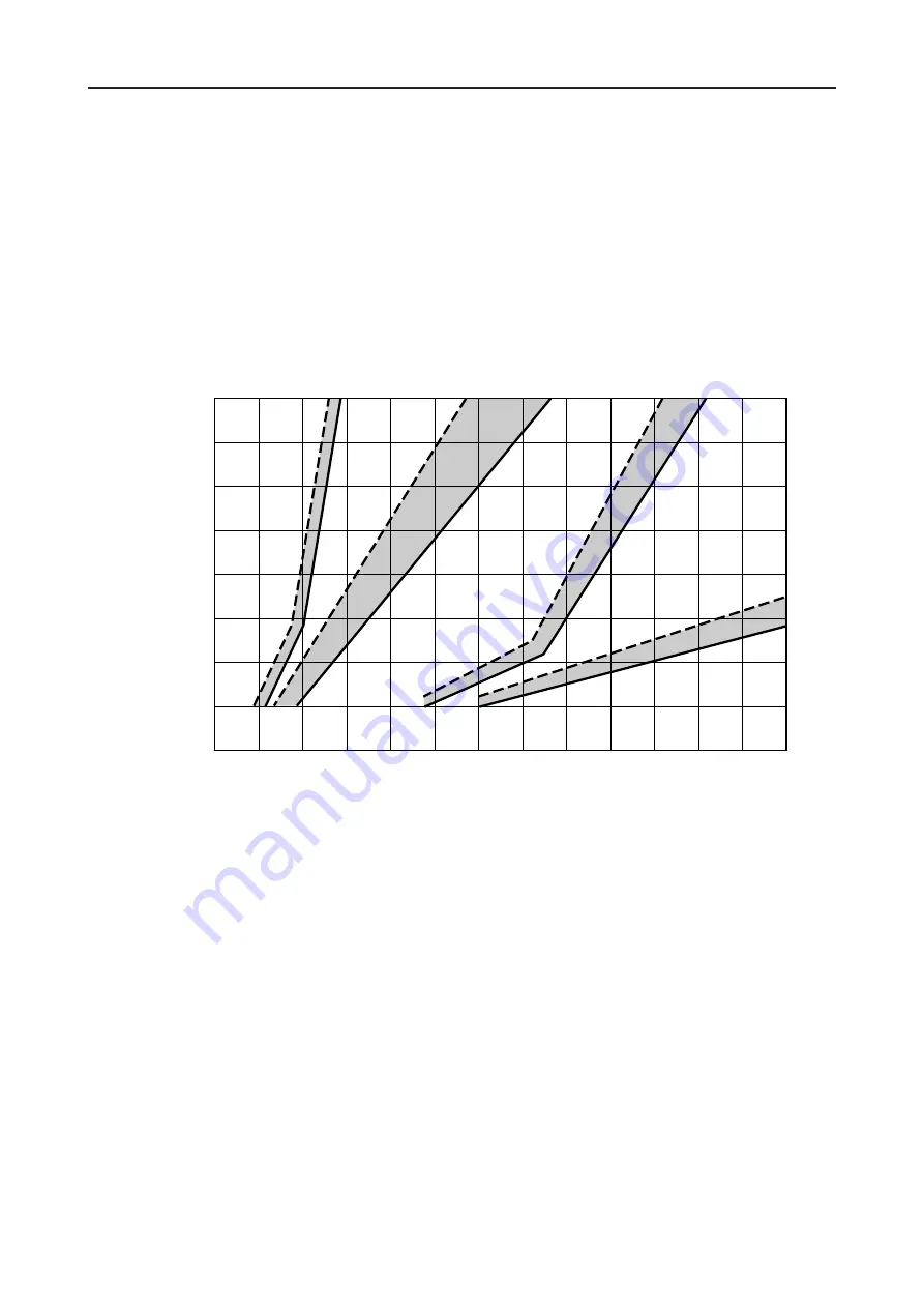
To give some guidance regarding the performance of various cross sections and lengths of cables, figure
7a is provided.
With the leads strapped together the Foster PCITS2000/2 will deliver 2000 A for all dimensions falling into
zones A and B, but for leads apart zone A only is achievable. Likewise with leads strapped together 1000 A
may be delivered for all cable dimensions in zones A, B, C and D, but for leads apart zones A, B and C
only are achievable.
Note:
1
The graph shows results of tests conducted with a short-circuit load. No allowance is made for breaker
or current transformer impedance. The length of the leads is defined as being from the PCITS to the
load (not twice that).
2
The upper- and left-most edges of the delimiting curves correspond to operation at 70˚C, the others to
operation at 20˚C.
3
For operation at or below 1000 A use the 6 V 1000 A setting.
4
These curves are based on nominal performance of the PCITS2000/2, to give guidance in the selection
of suitable test leads.
19
1
100
200
300
Area (mm
2
)
70
°
C
20
°
C
2
3
4
5
6
7
8
9
10
Length (m)
A
B
C
D
Figure 7a
Содержание PCITS2000/2
Страница 1: ...M PCITS600 2 PCITS2000 2 Primary Current Injection Test Sets User Guide Benutzerhandbuch...
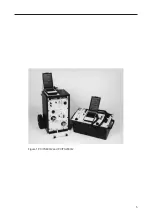
Страница 5: ...5 Figure 1 PCITS600 2 and PCITS2000 2...
Страница 23: ...23...
Страница 37: ...37...
Страница 38: ...38...

