background image

51

F.2 

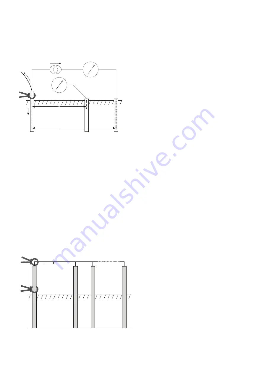
Principle of operation (three-terminal resistance measurement using ART)

The classic three-terminal test method has a disadvantage, namely that the electrode under test must be disconnected from the system 
it is supposed to protect in the event of a power system fault. The reason for this is that the injected test current will take all possible 
routes to ground and not all of it will necessarily flow through the electrode under test. In this case, the instrument will make a reading 
of the entire earthing network, not just the individual electrode.

By using a current transducer (the Megger ICLAMP) to measure the current flowing through the electrode under test as a fraction of the 
total test current injected, the instrument can determine the individual resistance. This arrangement is shown below:

A

Earth electrode 

under test

Connection 

to rest of system

B

C (H)

P (S)

X (E)

I2

I1

Potential stake

ICLAMP

Current stake

V

I

 schematic for three-terminal resistance measurement using

In this configuration, the injected test current I splits along two paths into I1 (flowing into the connected earthing system) and I2 
(flowing into the electrode under test, i.e. I=I1+I2. The resistance of the electrode under test is calculated as R=V/I2 or R=V/(I-I1). The 
current transducer (ICLAMP) measures I2 and feeds this value back to the instrument.

F.3 

Principle of operation (two-clamp stake-less resistance measurement)  

MFT1835 only

In this example, the electrode under test is connected to a network of other electrodes. It is either
impractical or unsafe to disconnect an individual electrode for testing. Also, there might be insufficient space to perform a classic three-
terminal resistance measurement. The stake-less test method using both VCLAMP and ICLAMP can be used to obtain a measurement 
for the electrode under test.

A defined test voltage is injected into the system using the VCLAMP, inducing a current, I, to flow and be measured by the ICLAMP. The 
model shown in Figure 7 can be simplified to the resistance of the electrode under test, Rx and the resistance of the other electrodes in 
parallel, i.e. R1 || R2 || … || Rn.

Therefore, the current induced by the test voltage is I=V/[Rx+(R1 || R2 || … || Rn)]. It follows that as the resistance of the other electrodes 
in parallel approaches zero, then the resistance measured, approaches the value of the electrode under test.

Earth electrode 

under test

Connection 

to rest of system

X (E)

I

I

V

R2

R1

Rx

ICLAMP

VCLAMP

Rn


schematic for two-clamp stake-less resistance measurement

Содержание MFT1800 series

Страница 1: ...1 M MFT1800 series Multifunction testers User manual ...

Страница 2: ...nsulation test lock 19 6 3 Measurement methods and sources of error 20 7 Loop Impedance testing 21 7 1 Range selection and test leads 21 7 2 MAKING A LOOP IMPEDANCE MEASUREMENT 23 7 3 Phase to Neutral or Phase to Phase testing 28 7 4 Prospective Fault Current and Short Circuit calculation PFC PSCC 29 7 5 Measurement methods and sources of error 30 8 Residual Current Device testing 31 8 1 MAKING AN...

Страница 3: ...arning 49 11 5 Invalid rotary switch setting 49 11 6 Continuity test 49 11 7 Insulation test 49 11 8 RCD Test 49 11 9 RCD range selection errors 50 11 10 Loop Test 50 11 11 Earth test 50 11 12 Test will not start 50 Appendix A Sending Storing Deleting and Recalling Test Results 52 Appendix B Downloading data using Bluetooth 55 Appendix C Installation category definitions 57 Appendix D Safe working...

Страница 4: ...ells and attempt to charge the cells This can cause explosion or fire Do not operate the charging equipment supplied with the MFT1835 in damp or wet environments or outside All test leads must be removed from the instrument while charging After insulation tests capacitive circuits must be allowed to discharge before disconnecting test leads Locking the Insulation test ON should only be used where ...

Страница 5: ...hrough fuses that are rated to handle the likely maximum fault voltages and currents that could be encountered at the installation NOTE THE INSTRUMENT MUST ONLY BE USED BY SUITABLY TRAINED AND COMPETENT PERSONS Users of this equipment and or their employers are reminded that Health and Safety Legislation requires them to carry out valid risk assessments of all electrical work so as to identify pot...

Страница 6: ...ms with rated voltages up to 300 Volts a c rms to earth ground 2 Overview 2 1 Front panel and controls MFT1815 MFT1825 1 Mode Test button Lead null Test lock Display backlight Display Primary functions Secondary functions Test button Lead null Test lock Set up selector Touch voltage contact point MFT1825 Mode Test button Lead null Display Primary functions Secondary functions Test button Lead null...

Страница 7: ...ment capability test is inhibited Type AC RCD selected Rp Rs Potential stake P stake resistance exceeds range for accurate measurement Type A RCD selected Rc RH Current stake C Stake resistance exceeds range for accurate measurement Type S RCD Type AC V Ground noise voltage exceeds range for accurate measurement of resistance Type S RCD Type A V VCLAMP error Type B RCD selected I ICLAMP error Fast...

Страница 8: ...atteries the battery indicator in the display will show NiMH under the battery status symbol as below Feature available on all models To replace batteries or fuse Switch off the instrument Disconnect the instrument from any electrical circuits Remove the battery cover from the base For battery replacement a Remove old cells and refit new batteries following correct polarity as marked on the batter...

Страница 9: ...nd may cause personal injury Ensure ambient temperatures are between 4ºC and 40ºC while charging the MFT Note The crossed out wheeled bin placed on the batteries is a reminder not to dispose of them with general waste at the end of their life Spent Alkaline and NiMH batteries are classified as Portable Batteries and should be disposed of in the UK in accordance with Local Authority requirements Fo...

Страница 10: ... To lock the test button hold down either of the RED test lock buttons with the Lsymbol whilst holding down the test button If is displayed the right hand buttons perform a scrolling function 3 2 Mode button functions The function of the mode button is dependent on the test function selected Test selected Function Options Comments V mVºC Volts mv model specific Temperature Temperature requires a s...

Страница 11: ...figuration Supply voltage over range or under range Supply Frequency out of specification 3 3 4 RCD testing Touch voltage detected or predicted to exceed 50 V or 25 V depending on instrument configuration Supply voltage over range or under range Supply Frequency out of specification 3 3 5 Earth testing External voltage greater than 25 V present Leads not corrected connected as per the test require...

Страница 12: ...3 terminals L1 L2 L3 N E OR if Using the Mains plug Lead L1 N E Note When all three test leads eg Phase Neutral and Earth or the mains plug test leads are connected the voltage displayed is the highest of the three possible voltages and the supply frequency is shown in the secondary display Pressing the TEST button will sequence through the individual L E N E and L N voltages On models with a dedi...

Страница 13: ...ation L1 L2 L3 4 4 Leakage current measurement Leakage current measurement uses the optional accessory current clamp ICLAMP 1 On the MFT1825 and 1835 set the primary left hand knob to RE and the secondary right hand knob to A 2 Connect to ICLAMP part No ICLAMP to the ICLAMP socket on the MFT 3 Connect the clamp to the circuit conductor The instrument will display the ac current flowing in the cond...

Страница 14: ...ature can be made with the remote switch probe Tests are automatic and do not require the test button to be pressed 1 Connect the switch probe to the switch probe socket The probe replaces the standard RED test lead and can now be used as a normal test probe L1 L2 L3 N E ...

Страница 15: ... circuit in both directions and the highest measured value being displayed See section 10 SETUP OPTIONS 5 1 Nulling test lead resistance up to 9 99ohms W Before starting a continuity test the test lead resistance should be nulled such that it does not add extra resistance to the circuit being measured Once nulled it does not need repeating for each test Periodically it should be checked to ensure ...

Страница 16: ...tance of 99 9kΩ is present Circuit voltages in excess of 4V are detected 5 3 Storing downloading results MFT1835 only For full details see Appendix B Once the display shows a value it will automatically be logged into temporary memory Unless stored this will be over written by the next measurement To store this result or to send it to a PowerSuite compatible device refer to Appendix B 5 4 Continui...

Страница 17: ... test requirements Refer to the SETUP section 10 of this guide Selectable limits of 0 5W 1W 2W 5W 10W 20W 50W 100W depending on model are available This setting is stored even when the instrument is switched off 5 7 Measurement methods and sources of error Method of measurement The 2 wire lead set must be used for this measurement A d c voltage of nominally 4 4 V with a current limit of 200mA is u...

Страница 18: ...eading has settled Circuit will now discharge safely Note A 1000V warning is displayed whenever the 1000V range is selected for the first time and the TEST button is pressed 6 2 Insulation test lock To lock an insulation test ON hold down either of the TEST buttons followed by either of the RED LOCK buttons Hold down the TEST button then press the red LOCK button To release the Locked on insulatio...

Страница 19: ...d of measurement The selected dc test voltage current limited to less than 2mA d c is applied to the circuit under test and the resistance is calculated from measurements of the resulting voltage and current Capacitive circuits can take some time to charge This is displayed as an increasing voltage that takes longer to reach its maximum than normal The reading is stable with a circuit capacitance ...

Страница 20: ...These are automatically performed and the end result is displayed Test Lead Null The MFT does not need the resistance of the test leads to be nulled for this test They are already calibrated into the measurement circuit at 0 07W However if using fused leads or 3rd party test leads the resistance of these leads may be different In this case they can be measured using the continuity test and the res...

Страница 21: ...n not available Where to use On RCD protected circuits where access to all three conductors is not possible Note 2Lo is not available when all three leads are connected as the 3Lo is the preferred measurement mode Selecting the test mode To switch between Loop test modes press the Function button as below Press the function key to change between 3Lo 2Hi and 2Lo The test mode is displayed as below ...

Страница 22: ...rth terminals 2 Press the Function key to select the 2Hi mode The RCD will not trip so there is no need to use the 3Lo and 2Lo modes 3 Connect test leads as below with the Red test lead connected to the L1 Red terminal on the MFT and the Green test lead connected to the Green L2 terminal L N E MCB RCD g 4 Press TEST to start the test sequence This can be automated in SETUP so the test starts when ...

Страница 23: ...bol The loop impedance reading may have been compromised by the circuit interference Repeat the test 7 2 2 Zs and Zdb loop measurements without an RCD eg Zs Zdb etc 1 Set the LEFT rotary range knob to the L PE range 2 Press the Function key to select the 2Hi mode 3 Connect test leads as below with the Red test lead connected to the L1 Red terminal on the MFT and the Green test lead connected to th...

Страница 24: ...CD will not trip If there is a risk associated with tripping an RCD alternative methods should be used for testing the circuit Using 3 wire measurement 3Lo 1 Set the LEFT rotary range knob to the L PE range 2 Press the Function key to select the 3Lo mode 3 Connect test leads as below with the Red test lead connected to the L1 Red terminal on the MFT the Green test lead connected to the Green L2 te...

Страница 25: ...Press TEST to start the test sequence 5 On completion of the test the display will show the loop resistance on the large display segments and the fault current on the small display segments 7 3 Phase to Neutral or Phase to Phase testing Note Only the 2Hi mode is available on this range 1 Set the LEFT rotary range knob to the L N L L range 2 Connect the test leads to the circuit as below with the R...

Страница 26: ...oltage 75V 55V 75V and 150V 110V 150V and 300V 230V 300V 400V 7 5 Measurement methods and sources of error Method of measurement During a loop test the instrument measures the difference between the unloaded and loaded supply voltages From this difference it is possible to calculate the loop resistance The test current will vary from 15mA to 5A depending on supply voltage and the loop resistance v...

Страница 27: ... by Use the two wire lead set with prods and making a firm connection to clean conductors Make several tests and taking the average Ensure that potential sources of noise in the installation are isolated switched off eg automatically switched loads or motor controllers ...

Страница 28: ...test the following RCD types AC A S and Programmable typically a type A RCD with variable disconnection time The MFT1825 and MFT1835 can also test Type B RCDs RCD Type AC A S B Description Operate with AC residual earth currents only Operate with AC and pulsed DC residual earth currents Selective RCD Operates on type AC with time delay or type A with time delay Operate with AC Pulsed DC and Smooth...

Страница 29: ...ng This is printed on the RCD 10mA 30mA 100mA etc Select the RCD type either AC A S or B by pressing and HOLDING DOWN the mode button for 2 seconds whilst in RCD test mode Repeat until the RCD type is displayed Refer to table above for symbol options and descriptions Note Type B RCD testing is not available on MFT1815 8 3 x I RCD Current Rating No trip test 1 Set the LEFT rotary range knob to the ...

Страница 30: ...999ms RCD Passed 8 4 1 x I RCD Current Rating Tripping test on 30mA RCD 1 Set the LEFT rotary range knob to the l RCD test range 2 Connect the instrument as in 8 3 above 3 Press the mode button to select 0º 4 Press the TEST button X Touch voltage limit Measured touch voltage RCD Trip time No trip RCD Type RCD Test mode any value below 300ms indicates an RCD has tripped in an adequate time 5 Press ...

Страница 31: ...the above test Record the higher of the two values 150 ms RCD FAILED no trip 150 ms RCD Passed 8 6 5 x I RCD Current Rating Tripping test on 30mA RCD Repeat the test sequence in 8 5 but with the LEFT rotary range knob to the 5I RCD test range 1 Press the mode button to select 0º 2 Press the TEST button The Display should show the following X Touch voltage limit Measured touch voltage RCD Trip time...

Страница 32: ...ion 10 The fast ramp test tests that the RCD will trip between 1 2I and 1xI of the rated RCD trip current This allows faster testing and higher test currents to be used repeatedly without overheating the instrument The duration of each ramp step is less than the 300ms required in EN 61557 As such this test should not be used if compliance to EN61557 is required Testing is the same as the standard ...

Страница 33: ...e left range knob and the current rating of the RCD on the right range knob 5 Press the TEST button 6 The RCD should trip and display the trip time in ms The Touch Voltage is displayed on the small digital readout Notes Only 1 x I is available Selecting other test currents will reset the test type to AC Only 10mA 30mA 100mA and 300mA test options are available on DC testing The tripping current of...

Страница 34: ...e table above will be performed Each time the RCD trips it should be reset The MFT automatically detects the reset and continues testing until the RCD stops tripping The MFT will display END 5 Return to the MFT and press the mode button to scroll through the test results in sequence 8 13 3 Phase RCD testing The MFT1800 series is designed to test RCDs on 3 phase installations To test RCDs in a 3 ph...

Страница 35: ...25V 50V 60V Notes The touch voltage is always displayed using the nominal trip current of the RCD ie 1xI If using the 1 2xI 2xI or 5xI test ranges the touch voltage will still be displayed for 1xI test current as per IEC 61557 6 2xI and 5xI can create real touch voltages during the test that are higher than the displayed value If this voltage exceeds the touch voltage limit UL the test will be sto...

Страница 36: ...xI All other RCDs only need to be tested at 1 2xI and 1xI Always press the RCD TEST button on the RCD to ensure the function works It is recommended the RCD test button is tested AFTER the timing tests above are complete This can identify RCDs that may stick or fail if not checked periodically ...

Страница 37: ...ction with the ICLAMP can be used to make stake less measurements of the earthing system For the principles of Earth resistance testing go to Appendix 9 1 Connection terminals The terminal references used on the MFT are MFT1800 H E S The terminal colours correspond to the Earth test lead set not the standard test leads shipped with the MFT1800 MFT1835 Connection panel I CAT IV 300V 12 15V 1 2A H E...

Страница 38: ...ding is a c and may not be suitable for continuity testing according to some local regulations 9 4 Making a measurement Three terminal resistance measurement 1 Connect the instrument as below I CAT IV 300V 12 15V 1 2A Electrode under test Potential stake Current stake 2 Set the rotary selector switch to the 3P position 3 Press and release the TEST button The instrument will perform pre measurement...

Страница 39: ... may display a noise warning This means that interference has been detected which may impair the accuracy of the measurement In particular the reading could be lower than the actual resistance The resistance of the electrode or system must be verified by an alternative method Note The instrument will display the warning triangle and an excessive noise voltage indicator if the ground noise voltage ...

Страница 40: ...ed the main display shows Err momentarily with REV on the auxillary display together with the V clamp symbols 5 Ensure a minimum separation of 100 mm between the ICLAMP and VCLAMP 6 Set the rotary selector switch to the position 7 Press and release the TEST button The instrument will perform pre measurement checks the status of which will be indicated on the display 8 The stake less resistance rea...

Страница 41: ...rent loop test ON OFF ON RAS RCD AUTO start ON OFF OFF RRA 3 RCD Ramp test Nor Normal FST Fast Nor FST Nor UL Touch voltage limit 25V 50V 60V 50V N L Reverse Polarity Loop test enable ON Loop test allowed OFF Loop test stopped ON OFF OFF OFF Auto switch OFF in minutes 2m 10m off 20minutes bAt Alkaline or NiMH selection 1 5V or 1 2V Depending on instrument StR Store mode IN Internal Bt Bluetooth on...

Страница 42: ...Insulation test 1000V 1000V Flashing warning before 1kV test VOL 0 L Voltage overload during test 11 8 RCD Test trp Supply tripped unexpectedly 50V Test aborted due to danger of exceeding touch voltage limit Err con Hardware problem detected during High Current Loop test or RCD test 11 9 RCD range selection errors ERR 1000mA Requested current is 1000mA ERR Type A In Type A mode Instrument has been...

Страница 43: ...amp symbol During an ART test the I clamp is the wrong way round Err Rp symbol Rp resistance is too high Err Rc symbol Rc resistance is too high 11 12 Test will not start CON Wrong connection to instrument hot Internal resistors are too hot Also shows thermometer Hot Internal heat sink is too hot Also shows thermometer VOL 280V for example Supply voltage is too high L N 48V for example Voltage on ...

Страница 44: ...Right Lock RIGHT TEST buttons to scroll through the values until the one you need is reached 4 Press and release the Bluetooth Lock button again to display each of the remaining options Job Distribution Board Circuit Phase and use the Right Lock RIGHT TEST buttons to change these values as required 5 To complete the store press and hold the Bluetooth Lock button until Str Ok is displayed Notes 1 I...

Страница 45: ...erform an Insulation test as described previously 2 Press and hold the Bluetooth Lock button to display the first option Release button when L E displayed 3 Use the Right Lock RIGHT TEST buttons to scroll through the options until the one you need is reached L E L n n E L L or 4 Press the Bluetooth Lock button to send the test result to your PC or mobile device The display chevrons will alternate ...

Страница 46: ...e whilst the connection is being established When connected the Bluetooth symbol will flash whilst the result is transmitted 5 The test results will now appear in the correct box in the certificate open on your PC or mobile device RCD Testing 1 Perform a RCD test as described previously 2 and hold the Bluetooth Lock button again to send the test result to your PC or mobile device The MFT test resu...

Страница 47: ...n the Add Bluetooth Device wizard You will be prompted during the pairing process to enter your passkey enter 1234 During the pairing process you may also be prompted to enable the Bluetooth Serial Port Ensure this option is chosen if you are given this option 7 Once you have clicked Finish on the wizard on the PC Laptop the pairing process will now be complete and your PC Laptop pairing code will...

Страница 48: ... 7 On the Windows Mobile 5 press the left hand menu button four times to select the following in sequence Next OK Next and Done 8 Continue to press the left hand button until you return to the windows desktop display Bluetooth Pairing Palm v5 1 Set the MFT Range knob to the Bluetooth SET UP position 2 Press the Bluetooth Lock button on the MFT the MFT will show if no pairing exists or the last thr...

Страница 49: ... to show paired devices iii Select the top left hand menu button then the New Paired devices symbol Note If there is a MFT symbol present check that it has the serial number displayed as your MFT If this isn t the case then delete the MFT from the Symbian and continue with the pairing procedure 4 Push the Bluetooth Lock button again to start the pairing process the MFT will display 5 Once paired s...

Страница 50: ...by an approved Megger service or by Megger instruments Limited To clean the instrument use a damp cloth or isopropyl alcohol if available To clean the display window only use a lint free cloth For warranty repairs see appendix E Appendix F Earth resistance testing Basic principles F 1 Principle of operation three terminal resistance measurement The classic fall of potential test is used to accurat...

Страница 51: ... under test i e I I1 I2 The resistance of the electrode under test is calculated as R V I2 or R V I I1 The current transducer ICLAMP measures I2 and feeds this value back to the instrument F 3 Principle of operation two clamp stake less resistance measurement MFT1835 only In this example the electrode under test is connected to a network of other electrodes It is either impractical or unsafe to di...

Страница 52: ...r products Returning your product to Megger UK and USA service centres 1 When an instrument requires recalibration or in the event of a repair being necessary a Returns Authorisation RA number must first be obtained from one of the addresses shown above You will be asked to provide the following information to enable the Service Department to prepare in advance for receipt of your instrument and t...

Страница 53: ...trinsic accuracy 5 3digits Display range 0 01 W to 1000 W Supply 48 V to 500 V 45 Hz to 65 Hz Test Current High 4 0 A 230 V PSCC Range 20 kA EN61557 Range 0 30 W to 1000 W Max Service error 10 2 digits Loop test 3Lo 2Lo L E Intrinsic accuracy 0 01 W to 39 9 W 5 5digits 40 0 W to 1000 W 10 5digits Display range 0 01 W to 1000 W Supply 48 V to 280 V 45 Hz to 65 Hz Test Current Pulsed PFC Range 20 kA...

Страница 54: ...C Environmental Specification Temperature Operational range 10 C to 55 C Storage range 25 C to 70 C Humidity Operating Humidity 90 R H at 40 C max Altitude 2000m to full safety specification Weight 1000g 10 including batteries but excluding test leads accessories and carry case IP rating IP54 Power Supply Battery Primary 6 x 1 5 V cells IEC LR6 type AA alkaline Battery Rechargeable 6 x 1 2 VNiMH c...

Страница 55: ...7 Megger GmbH Obere Zeil 2 61440 Oberursel Germany T 06171 92987 0 F 06171 92987 19 Megger Pty Limited Unit 26 9 Hudson Avenue Castle Hill Sydney NSW 2125 Australia T 61 0 2 9659 2005 F 61 0 2 9659 2201 E ausales megger com This instrument is manufactured in the United Kingdom The company reserves the right to change the specification or design without prior notice Megger is a registered trademark...

Отзывы: