DER1 digital regulator instruction manual - rev. 03 - pag. 24
4) Two minutes later slowly rotate the AMP trimmer in the counter clockwise direction until there should be
a decrease in the voltage value of the generator and alarm 5 should come on (visible due to a change
in the flashing indicator light) .
5) Under these conditions, adjust the AMP trimmer, until the output voltage value is 97% of the nominal
value: alarm 5 is still activated.
6) Return to the nominal speed; alarm 5 should disappear in a few seconds and the generator voltage
should increase to the nominal value.
7) Adjust the trimmer as indicated in the following paragraph.
4. Underspeed
4.1 Description
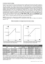
For speeds lower than a programmable threshold, the machine voltage is no longer constant, but is
regulated proportionately with the frequency at a ratio, which is also programmable, as shown in figure
8.
The intervention threshold depends upon:
•
the status of jumper 50/60 (terminals 25 and 26) if enabled from the
Configuration
Menu.
•
the status of the 50/60 setting in the
Configuration
Menu
•
the position of the Hz trimmer if enabled from the
Configuration
Menu
•
the value entered at parameter P[21]
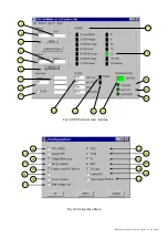
Activation of the function with voltage proportionate to the frequency is signalled by activation of alarm 6
(visible from the DSR Terminal control panel and due to a change in the flashing indicator light).
Parameter P[21]
(equivalent to the Hz trimmer) sets the Underspeed protection intervention threshold; if
this is set on 16384, the protection cuts in at 45 Hz (if the 50/60 jumper and 50/60 flag in the Configuration
Menu are not present) or at 54 Hz (if the 50/60 jumper is enabled or the 50/60 flag is active in the
Configuration Menu). Values between 0 and 16384 proportionately lower the threshold, respectively to 40
Hz and 48 Hz; values between 16384 and 32767 proportionately raise the threshold, respectively to 50 Hz
and 60 Hz.
Once the underspeed protection has intervened, the frequency is proportionately reduced, as indicated in
figure 8.
Parameter P[23]
sets the slope of the voltage/frequency curve; the default value is 9000. An
increase in the value of P[23] involves a greater reduction of the voltage as a function of the reduction in
frequency. A decrease in the value of P[23] involves a lower reduction of the voltage until the limit of P[23]
=0, which means that there is no reduction in voltage.
WARNING:
Overheating could occur, which is dangerous for the machine, if the voltage is not
lowered enough to decrease the excitation when the alternator is functioning at a reduced speed.
4.2 Calibration with a supervision unit
Use the following procedure in order to calibrate the underspeed protection:
1) If the machine has to operate at 60 Hz, make sure the bridge, between terminals 25 and 26 of
connector CN1, is inserted, if it is enabled from the
Configuration
Menu, or activate 50/60 from the
same menu.
2) If the Hz trimmer is enabled, the value of the protection intervention threshold is read at location L[34],
otherwise it is entered directly at parameter P[21].
The value 16384 entered at parameter P[21] (or read at location L[34]) corresponds to an intervention
at 45/54 Hz (depending on whether 50/60 is activated or not).
Values between 0 and 16384 correspond to an intervention that varies from 40/48 Hz to 45/54Hz.
Values between 16384 and 32767 correspond to an intervention that varies from 45/54 Hz to 50/60Hz.
3) When the speed drops below the threshold value, generator voltage begins to drop and the alarm is
shown simultaneously through the indicator light and DSR Terminal control panel.
4) By increasing speed, the generator voltage will normalise and the 6 alarm will disappear.
4.3 Calibration without a supervision unit
NOTE: This calibration can be performed only if the Hz trimmer and 50/60 jumper have been previously
enabled.
Use the following procedure in order to calibrate the under speed protection:
1) Rotate the Hz trimmer entirely in the counter clockwise direction.
2) If the machine has to operate at 60 Hz, ensure that the bridge is inserted between terminals 25 and 26
3) Bring the generator to 90% of the nominal speed.
Содержание DER1
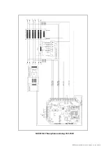
Страница 10: ...DER1 digital regulator instruction manual rev 03 pag 10 SCC0158 Three phase sensing 75V 150V...
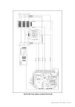
Страница 11: ...DER1 digital regulator instruction manual rev 03 pag 11 SCC0159 Three phase sensing 150V 300V...
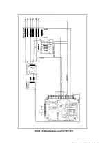
Страница 12: ...DER1 digital regulator instruction manual rev 03 pag 12 SCC0160 Single phase sensing 75V 150V...
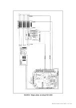
Страница 13: ...DER1 digital regulator instruction manual rev 03 pag 13 SCC0161 Single phase sensing 150V 300V...
Страница 14: ...DER1 digital regulator instruction manual rev 03 pag 14 SCC0202 Single phase sensing 300V 600V...

