DER1 digital regulator instruction manual - rev. 03 - pag. 30
DI1 COMMUNICATIONS UNIT
1. Description
The DI1 interface device (fig. 10) permits connection of the DSR/DER1 digital regulator to a programming
and monitoring device, whose functions may include the following:
-
Repetition, or visualisation, of the status variable of the generator, even from a remote location
-
Setting of single parameters
-
Uploading and downloading of settings files
-
Status readings (alarms, measured values)
-
Readings of information of the alarm memory
-
Interface conversion towards other field buses or communications networks
The DI1 interface must be positioned near the DSR or the DER1. The COM connector of the DSR/DER1
regulator is connected to the CN2 connector of the DI1 interface with the special cable supplied by Mecc
Alte. The programming and control unit may be made up of a PC, a PLC or other equipment, providing it
has at least one of the interfaces of the DI1 device.
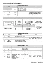
The following serial interfaces available on the DI1 communications unit are:
•
RS232 without handshake (3 wires) on CN3 connector
_____
•
RS485 two wires half duplex on CN4 connector (DTE
(1)
, Tx,RTSRx RTS )
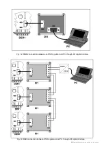
The connection between one DER1 regulator and a PC is shown in fig. 12.
When necessary, the DI1 interface permits insertion of the regulator in an RS485 network with other
regulators or devices of a different type, but with the same type of bus, as shown in fig. 13.
The DI1 interface also permits isolation of the A.P.O. contact of the regulator : terminal 24 of the DER1
must be connected to terminal 5 of CN1 (as indicated with the dotted line in fig. 11).
Two types of APO insulated contacts are available on connector CN5 (which cannot be used
simultaneously):
•
Solid state switch, Max. 30V - 100mA (terminals 3 and 4)
•
Electro-mechanical switch, 24Vdc/120Vac – 6A
(2)
(terminals 5, 6 and 7)
WARNING:
for the correct operation of the APO insulated contacts, the cable between the COM
connector
of the DSR/DER1 regulator and the CN2 connector of the DI1 interface MUST be connected.
Nota 1) DTE = Data Terminal Equipment
Nota 2) Current on resistive load
Fig. 10:
layout of the DI1 communications interface
Содержание DER1
Страница 10: ...DER1 digital regulator instruction manual rev 03 pag 10 SCC0158 Three phase sensing 75V 150V...
Страница 11: ...DER1 digital regulator instruction manual rev 03 pag 11 SCC0159 Three phase sensing 150V 300V...
Страница 12: ...DER1 digital regulator instruction manual rev 03 pag 12 SCC0160 Single phase sensing 75V 150V...
Страница 13: ...DER1 digital regulator instruction manual rev 03 pag 13 SCC0161 Single phase sensing 150V 300V...
Страница 14: ...DER1 digital regulator instruction manual rev 03 pag 14 SCC0202 Single phase sensing 300V 600V...

