


DER1 digital regulator instruction manual - rev. 03 - pag. 27
The status of active alarms is stored at location L[38], which can be read with the serial connection.
The index of bits that have a value of 1 corresponds to the active alarm. If the regulator is correctly
working (no alarm active) the bit 11 will be high.
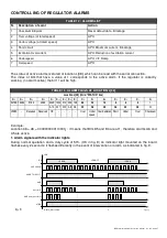
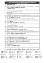
CONTROLLING OF REGULATOR ALARMS
N.
Description of event
Action
1
Checksum EEprom
Reset default data - Blockage
2
Over voltage (at rated speed)
APO
3
Under voltage (at rated speed)
APO
4
Short circuit
APO, Maximum current - Blockage
5
Excitation Overcurrent
APO, Reduction of excitation current
6
Underspeed
APO, V/F Ramp
7
Overspeed
APO
TABLE 12 : ALARMS LIST
TABLE 13 : ALARM FLAGS AT LOCATION L[38]
/
+
/
/
6
/
/
/
)
/
5
/
J
/
9
/
/
+
/
/
6
/
/
/
)
69J 6J
J5
)5
)J ) + + J
12
1
2
) 5 J
1
3
2
K+)2)
'
<.
'
'
'
'
<
H
<4-
H
<
3 0
$$)+ 4-5 678&
Example:
Location 38 = 48 = 0000000000110000
2
: it means that Bits B5 and B4 are at 1, therefore alarms A6 and
A5 are active.
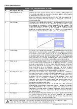
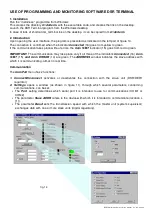
1. Alarm signals with the indicator lights
During normal operation and a duty cycle of 50% (OK in fig. 9) an indicator light mounted on the board
flashes every 2 seconds; it flashes differently in the event of intervention or alarm, as indicated in fig. 9.
OK
CHECKSUM
SHORT CIRCUIT
Hz or O.S.
AMP
AMP and (Hz or O.S.)
STOP
Allarm intervention
1
2
t [sec]
LED
LED ON
LED OFF
LED ON
fig. 9
Содержание DER1
Страница 10: ...DER1 digital regulator instruction manual rev 03 pag 10 SCC0158 Three phase sensing 75V 150V...
Страница 11: ...DER1 digital regulator instruction manual rev 03 pag 11 SCC0159 Three phase sensing 150V 300V...
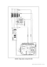
Страница 12: ...DER1 digital regulator instruction manual rev 03 pag 12 SCC0160 Single phase sensing 75V 150V...
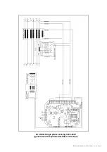
Страница 13: ...DER1 digital regulator instruction manual rev 03 pag 13 SCC0161 Single phase sensing 150V 300V...
Страница 14: ...DER1 digital regulator instruction manual rev 03 pag 14 SCC0202 Single phase sensing 300V 600V...


