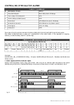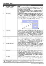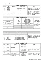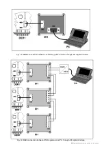
DER1 digital regulator instruction manual - rev. 03 - pag. 22
1.3 Slow voltage variations
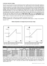
In the event of rapid variation of the reference, a procedure of "slow" variation has been foreseen: in
response to a step variation, parameter P[18] determines the rapidity with which the transition is made.
A value of 1 involves the slowest possible variation; a value exceeding 100 involves an almost immediate
variation. The value 0 disables any variation.
2. Stability
2.1 Adjustment of stability
The proportional gain (to voltage error) of the regulator takes its value either from the position of the
STAB
trimmer, if it has been enabled from the
Configuration
Menu, or from parameter P[20], whose value
varies from 0 to 32767. Do not set this trimmer in a position lower than two notches counted
counterclockwise.
Integral gain depends on the proportional gain according to the value entered in parameter P[13] (a value
of 0 corresponds to an integral gain of nil, while a value of 32767 corresponds to an integral gain
commensurate with the proportional one).
Each of the two gains can be multiplied by a coefficient, which can be a value of 1, 2, 4, 8, 16, 32 or 64,
according to the value entered in parameter P[11] (for proportional gain) and P[12] (for integral gain). This
value represents the exponent assigned to base 2 (fixed) to obtain the desired gain (i.e. parameter P[11] =
4 = > coefficient = 2
4
= 16).
The regulator diagram is shown in figure 6.
K
P
K
I
s
+
+
+
-
Ref.
Feedback
Error
PI
out
figure 6 :
Regulator Diagram
3. EXCITATION OVERCURRENT
3.1 Description
The DER1 regulator is equipped with an excitation (main rotor) winding temperature estimator. An
estimate of the temperature is memorised in real time (and can be read) at location L[45]. The progress of
the temperature is of the exponential type (see figure 7).
Through parameter P[22] or the AMP trimmer, it is possible to define a limit (which involves intervention of
alarm 5) to the excitation voltage and therefore to the temperature.
The function of this alarm is not only to signal an excessive temperature, but it also has an active function
in reducing the cause. In fact, an adjustment ring takes control of the voltage generated when the
threshold set is exceeded: This reduces the voltage to the point of reducing the excitation current by a
value compatible with the ability of thermal dissipation of the machine. The stability of the adjustment in
the event of over-excitation alarm can be set with parameters P[28] and P[29]. The default values are
suitable for the great majority of machines.
If the magnetic gain of the alternator is high, unstable situations can be created upon
intervention of the protection, therefore it is necessary to adjust parameters P[28] and P
[29] (in general it is sufficient to lower parameter P[28] ).
16384
21065
P19
210V
230V
P18 = 20
P18 = 1
t
t
P18 = 100
Vo
fig. 5
Содержание DER1
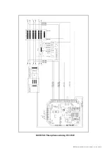
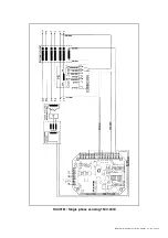
Страница 10: ...DER1 digital regulator instruction manual rev 03 pag 10 SCC0158 Three phase sensing 75V 150V...
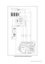
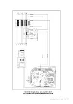
Страница 11: ...DER1 digital regulator instruction manual rev 03 pag 11 SCC0159 Three phase sensing 150V 300V...
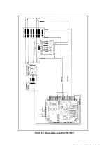
Страница 12: ...DER1 digital regulator instruction manual rev 03 pag 12 SCC0160 Single phase sensing 75V 150V...
Страница 13: ...DER1 digital regulator instruction manual rev 03 pag 13 SCC0161 Single phase sensing 150V 300V...
Страница 14: ...DER1 digital regulator instruction manual rev 03 pag 14 SCC0202 Single phase sensing 300V 600V...

