Page 18
Installation
optoNCDT ILR 1181 / 1182
Pin Color
Assignment
ILR 118x-30(01)/RS232 ILR 118x-30(01)/RS422
H
M
G
J
K
A
L
B
C
D
E
F
view on solder pin side, 12-pole
female cable connector
A
white
TxD
RX+
B
brown
RxD
RX-
C
green
TRIG
D
yellow
signal I
OUT
(4 ... 20 mA)
E
grey
---
TX-
F
pink
---
TX+
G
red
power supply 10 ... 30 VDC
H
black
alarm/digital switching output
J
violet
signal ground
K
grey/pink
n.c.
L
red/blue
power supply ground
M
blue
n.c.
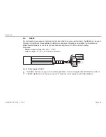
Fig. 6 Pin assignment
“Ground“ wires are connected to an internal collective ground point. They provide the reference potential for
all voltage values quoted below.
The limiting values of voltages, load rates and logic levels are in accordance with RS232 and RS422 standard
requirements. All outputs are protected against steady short-circuit currents.
A power supply and output cable extension is possible. One should, however, observe some important rules,
depending on the particular application scenario:
5.3.1
ILR 1181-30
Keep the RxD and TxD data lines as short as possible in all cases, because they tend to have an interference
emitting and interference receiving effect, notably, when in open state. Especially in environments with strong
spurious radiation there may be faults that may in some cases require a reset (turning the sensor off and on
again).
If the RS232 interface communication is not required after parameterization, you should provide for a termina-
tion wiring.


