Page 25
Operation
optoNCDT ILR 1181 / 1182
6.4
Analog Output
Properties: Current output
- 4 mA...20 mA
- Distance range limits can be set
- Behavior on error report can be preselected: 3 mA or 21 mA
-
Load resistance: ≤ 500 Ω against GND
- Accuracy: ±0.15 %
- Max. temperature drift: 50 ppm/K
- Resolution: 16 bit DA-converter
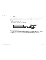
U
V
GND
red
red/blue
yellow
4 ... 20 mA
R
L
≤ 500 Ω
Fig. 15 Wiring diagram of analog output
The purpose of the analog output is to allow transmission of analog measured values via a 4 ... 20 mA inter-
face.
The amount of current which is injected into the line of transmission is proportional to the distance measured.
A given range of distances can be selected for transmission via the two parameters Range Beginning (RB)
and Range End (RE), see Chap.
7.3.10
, see Chap.
7.3.11
.
RE may be greater or smaller than RB.
The amount of injected current can be calculated as follows:
- RE > RB: IOUT [mA] = 4 mA + 16*((Distance - RB) / (RE - RB)) mA
- RE < RB: IOUT [mA] = 20 mA - 16*((Distance - RE) / (RB - RE)) mA

