74
IMM AGS-2
System Maintenance
General
On initial start-up and periodically during operation, it will be necessary to perform certain
routine service checks. Among these are checking the liquid line sight glasses, and the
compressor oil level sight glass. In addition, check the MicroTech II controller temperature
and pressure readings with gauges and thermometers to see that the unit has normal
condensing and suction pressure and superheat and subcooling readings. A recommended
maintenance schedule is located at the end of this section.
A Periodic Maintenance Log is located at the end of this manual. It is suggested that the
log be copied and a report be completed on a regular basis. The log will serve as a useful
tool for a service technician in the event service is required.
Initial start-up date, vibration readings, compressor megger readings and oil analysis
information should be kept for reference base-line data.
Compressor Maintenance
Since the compressor is semi-hermetic, no yearly compressor maintenance is normally
required; however, vibration is an excellent check for proper mechanical operation.
Compressor vibration contributes to a decrease in unit performance and efficiency and
indicates that maintenance is required. It is recommended that the compressor be checked
with a vibration analyzer at, or shortly after, start-up and again on an annual basis. The load
should be maintained as closely as possible to the load of the original test and only one
compressor should be running at a time. The initial vibration analyzer test provides a
benchmark of the compressor and, when performed routinely, can give a warning of
impending problems.
Lubrication
No routine lubrication is required on AGS units. The fan motor bearings are permanently
lubricated. No further lubrication is required. Excessive fan motor bearing noise is an
indication of a potential bearing failure.
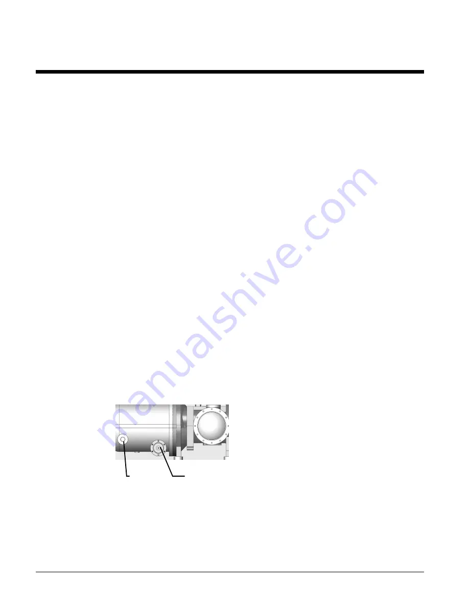
Figure 43, Compressor Oil Filter
Compressor oil must be ICI RL68HB, McQuay Part
Number 735030446 in a 1-gallon container. This is
synthetic polyolester oil with anti-wear additives and
is highly hygroscopic. Care must be taken to
minimize exposure of the oil to air when charging oil
into the system.
The oil filter resides in the compressor
housing as shown in Figure 43. Units without a
suction service shutoff valve require pumping down
the circuit in order to change the filter.
The top of the oil level should be visible in the sight glass. If the glass is completely filled
with oil at all times, the circuit is overcharged with oil. If only refrigerant is visible in the
glass, the circuit has insufficient oil.
A mechanical oil pressure differential switch is mounted on the unit frame adjacent to each
compressor and will shut down the compressor at a differential pressure greater than 25 psi.
Oil Filter
Housing
Oil
Sight
Glass


