background image

ON-BOARD DIAGNOSTIC 

06–02–5

06–02

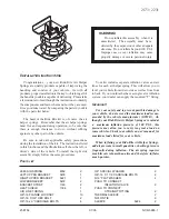
DLC-2 CONSTRUCTION

CHU060201038S06

A DLC-2 connector conforming to ISO (International Organization for Standardization) standards has been 
added.

Shape and terminal arrangement as stipulated by the ISO 15031-3 (SAE J1962) international standard has 
been adopted for this connector. The connector has a 16-pin construction that includes the CAN_H, CAN_L, 
GND1, GND2 and B+ terminals.

End Of Sie

Terminal

Function

CAN _L

Serial communication terminal (Lo)

CAN_H

Serial communication terminal (Hi)

GND1

Body GND terminal

GND2

Serial communication GND terminal

B+

Battery power supply terminal

B+

CAN_L

GND1

CAN_H GND2

DLC-2

CHU0602S002

Содержание 2004 RX-8

Страница 1: ...zda Motor Corporation reserves the right to alter the specifications and contents of this manual without obligation or advance notice All rights reserved No part of this book may be reproduced or used in any form or by any means electronic or mechanical including photocopying and recording and the use of any kind of information storage and retrieval system without permission in writing Mazda Motor...

Страница 2: ...ersion to SI Units Système International d Unités 00 00 8 Rounding Off 00 00 8 Upper and Lower Limits 00 00 8 SAE STANDARD 00 00 9 End of Toc AIM OF DEVELOPMENT CHU000000022S01 New Model Concept New four door four passenger sports car The Mazda RX 8 is an entirely new concept in a state of the art sports car combining unique sports car styling and excellent driving performance together with the co...

Страница 3: ...unique style Rotor motif shift lever knob and sunvisors employing mesh texturing demonstrate the value and attention to detail Comfortable interior Front and rear console boxes with cup holders Door pockets are provided for road maps or a small bag Sunvisors are equipped with illuminated vanity mirrors Premium audio system with nine BOSE speakers is available offering an acoustic space of high qua...

Страница 4: ... decreased in thickness and weight while maintaining high rigidity Spark plugs with iridium tips have been adopted for improved heat resistance and durability Flank cuts on the corners of the rotors provide improved exhaust efficiency by delaying the exhaust port closing timing Intake and control Sequential dynamic air intake system S DAIS has been adopted realizing powerful output at high engine ...

Страница 5: ...on and reduced fuel consumption Advanced front midship layout Combination of state of the art technologies such as a compact rotary engine a thin engine oil pan a forward located air intake system a compact air conditioning unit has produced a small and light powerplant package Adoption of an advanced front midship layout saddle shaped plastic fuel tank and an emergency puncture repair kit requiri...

Страница 6: ...loying five links per wheel has been adopted Excellent handling stability ride comfort and road noise performance have been realized by optimizing each link arrangement in consideration of geometry and compliance in order to maintain the optimum tire contact area at any time in the optimal condition against external forces during driving LARGE DIAMETER MONOTUBE SHOCK ABSORBER FORGED ALUMINUM LOWER...

Страница 7: ... by reducing the shift lever stroke Safety Lightweight and highly rigid safe body structure developed uniquely for the Mazda RX 8 has achieved high international standards of crash safety Reinforcement with high strength has been installed on the area equivalent to the center pillar on the rear doors realizing strength nearly equal to that of a center pillar of a standard sedan Dual inflator type ...

Страница 8: ...M 1 F E 1 7 N 4 1 2 3 4 5 6 Serial No 0 Hiroshima 1 Hofu 4 2004 5 2005 N 13B Standard power 3 13B High power FE Mazda RX 8 1 Drv Pass A B Side A B Curtain A B 7 Coupe JM1 Mazda passenger car 0 to 9 X Plant Model year Check Digit Engine type Body style Restraint system Vehicle type World manufacturer identification CHU0000S001 ...

Страница 9: ... specifications 210 260 kPa 2 1 2 7 kgf cm2 30 38 psi 270 310 kPa 2 7 3 2 kgf cm2 39 45 psi The actual converted values for 2 7 kgf cm2 are 265 kPa and 38 4 psi In the first specification 2 7 is used as an upper limit so the converted values are rounded down to 260 and 38 In the second specification 2 7 is used as a lower limit so the converted values are rounded up to 270 and 39 End Of Sie Electr...

Страница 10: ...Identification CLS Closed Loop System PSP Power Steering Pressure CTP Closed Throttle Position PCM Powertrain Control Module 3 CPP Clutch Pedal Position PAIR Pulsed Secondary Air Injection Pulsed injection CIS Continuous Fuel Injection System CKP sensor Crankshaft Position Sensor AIR Secondary Air Injection Injection with air pump DLC Data Link Connector DTM Diagnostic Test Mode 1 DTC Diagnostic T...

Страница 11: ......

Страница 12: ...Center ABDC After Bottom Dead Center BBDC Before Bottom Dead Center BTDC Before Top Dead Center CAN Controller Area Network CCM Comprehensive Component Monitor DC Drive Cycle DLI Distributorless Ignition F P Fuel Pump FP1 Front Primary 1 FP2 Front Primary 2 FS Front Secondary HI High IC Integrated Circuit IG Ignition KAM Keep Alive Memory KOEO Key On Engine Off KOER Key On Engine Running L F Leadi...

Страница 13: ...et port adopted Improved idle fuel economy Jet air fuel mixing system adopted Reduced engine noise and vibration Oil filled engine mount rubber adopted A cooling fan with electric motor adopted Improved reliability A degassing type coolant reserve tank adopted An independent ignition control system with distributorless ignition coil adopted A battery duct adopted Improved durability A spark plug w...

Страница 14: ...W 20 ILSAC GF 3 COOLING SYSTEM Type Water cooled forced circulation Coolant capacity L US qt lmp qt 9 8 10 4 8 6 Water pump Centrifugal V ribbed belt driven Thermostat Type Wax Opening temperature C F 80 84 176 183 Full open temperature C F 95 203 Full open lift mm in 8 5 0 33 or more Radiator Type Corrugated fin Cooling system cap Cap valve opening pressure 73 3 103 3 0 748 1 053 10 63 14 98 kPa ...

Страница 15: ...L 4 RE6A L 5 Trailing side RE9B T 4 STARTING SYSTEM Starter Type Coaxial reduction Output kW AT 1 8 MT 1 4 CONTROL SYSTEM Neutral switch MT ON OFF CPP switch MT ON OFF SSV switch ON OFF APV position sensor Hall element ECT sensor Thermistor IAT sensor Thermistor TP sensor Hall element APP sensor Hall element MAF sensor Inside MAF Hot wire Front HO2S Zirconia element all range air fuel ratio sensor...

Страница 16: ...2 15 KOEO Key ON Engine Off Self test 01 02 15 KOER Key ON Engine Running Self test 01 02 15 PID DATA MONITOR AND RECORD 01 02 18 SIMULATION TEST 01 02 20 End of Toc ON BOARD DIAGNOSTIC OUTLINE CHU010200102S01 Features Block Diagram End Of Sie To meet the OBD II regulations Diagnostic test modes adopted Improved serviceability DTCs adopted KOEO KOER self test function adopted PID DATA monitor func...

Страница 17: ...rd device control simulation test active command mode Mode 09 Request vehicle information Full names Unit Fuel system loop status Refer to list below LOAD ECT C F Short term fuel trim Long term fuel trim Engine speed rpm Vehicle speed km h mph Spark advance IAT C F MAF g s Absolute TP AIR control status O2S location Input voltage from rear HO2S V Target A F fuel trim OBD requirement according to v...

Страница 18: ...P system Sending Freeze Frame Data The Freeze Frame Data monitor items are shown below Freeze Frame Data monitor table Not applicable Full names Unit DTC that caused required Freeze Frame Data storage Fuel system loop status Refer to list below LOAD ECT C F Short term fuel trim Long term fuel trim Engine speed rpm Vehicle speed km h mph Spark advance IAT C F MAF g s Absolute TP AIR control status ...

Страница 19: ...ut ON 1 CCM P0113 IAT sensor circuit high input ON 1 CCM P0117 ECT sensor circuit low input ON 1 CCM P0118 ECT sensor circuit high input ON 1 CCM P0122 TP sensor No 1 circuit low input ON 1 CCM P0123 TP sensor No 1 circuit high input ON 1 CCM P0125 Insufficient coolant temperature for closed loop fuel control ON 2 CCM P0126 Insufficient coolant temperature for stable operation ON 2 Thermostat P012...

Страница 20: ...oblem ON 2 CCM P0704 CPP switch input circuit problem ON 2 CCM P0850 Neutral switch input circuit problem ON 2 CCM P1260 Immobilizer system problem OFF 1 Other P1574 TP sensor output incongruent ON 1 CCM P1577 APP sensor output incongruent ON 1 CCM P1686 Metering oil pump control circuit low flow side problem ON 1 Other P1687 Metering oil pump control circuit high flow side problem ON 1 Other P168...

Страница 21: ...al stuck rich ON 2 HO2S P2401 EVAP system leak detection pump control circuit low ON 2 EVAP system P2402 EVAP system leak detection pump control circuit high ON 2 EVAP system P2404 EVAP system leak detection pump sense circuit range performance problem ON 2 EVAP system P2405 EVAP system leak detection pump sense circuit low ON 2 EVAP system P2406 EVAP system leak detection pump sense circuit high ...

Страница 22: ...O2S heater control circuit low The PCM monitors the rear HO2S heater control voltage when the PCM turns the rear HO2S heater off If the control voltage exceeds 25 of the battery voltage the PCM determines that the rear HO2S heater control circuit voltage is low P0038 Rear HO2S heater control circuit high The PCM monitors the rear HO2S heater control voltage when the PCM turns the rear HO2S heater ...

Страница 23: ...high input The PCM monitors the input voltage from the TP sensor No 1 when the engine is running If the input voltage is more than 4 8 V the PCM determines that the TP sensor No 1 circuit input voltage is high P0125 Insufficient coolant temperature for closed loop fuel control The PCM monitors the ECT after cold engine start If the ECT does not reach the specification in a certain period the PCM d...

Страница 24: ...at a misfire which can damage the catalytic converter or affect emission performance has occurred P0301 Front rotor misfire detected The PCM monitors eccentric shaft position sensor input signal interval time The PCM calculates the change of the interval time for each rotor If the change of interval time exceeds the preprogrammed criteria the PCM detects a misfire in the corresponding rotor While ...

Страница 25: ...vel 15 85 Battery voltage 11 0 14 6 V Ignition switch OFF P0443 Purge solenoid valve circuit problem The PCM monitors the purge solenoid valve control voltage when the PCM turns the purge solenoid valve off If the control voltage is less than 5 8 V the PCM determines that the purge solenoid valve control circuit voltage is low The PCM monitors the purge solenoid valve control voltage when the PCM ...

Страница 26: ...rcuit malfunction MONITORING CONDITION Shift lever position gear is not in neutral position Engine speed more than 2 500 rpm LOAD more than 40 0 P0505 Idle air control system problem The PCM cannot control idle speed at the target idle speed during the self test P0506 Idle air control system RPM lower than expected The PCM compares the actual idle speed with the target idle speed when the engine i...

Страница 27: ...the PCM determines that the metering oil pump control circuit has a problem on the low flow side P1687 Metering oil pump control circuit high flow side problem The PCM monitors the input signal from the metering oil pump switch when the metering oil pump stepping motor is less than the standard step If the input signal is on the PCM determines that the metering oil pump control circuit has a probl...

Страница 28: ...ut voltage is less than 0 3 V the PCM determines that the APP sensor No 1 circuit input voltage is low P2123 APP sensor No 1 circuit high input The PCM monitors the input voltage from the APP sensor No 1 when the engine is running If the input voltage is more than 4 8 V the PCM determines that the APP sensor No 1 circuit input voltage is high P2127 APP sensor No 2 circuit low input The PCM monitor...

Страница 29: ... input voltage from the rear HO2S when the following conditions are met If the input voltage is less than 0 4 V for 40 s the PCM determines that the rear HO2S signal remains rich MONITORING CONDITION ECT more than 70 C 158 F Engine speed more than 1 500 rpm MAF amount more than 10 g s 1 32 lb min Short term fuel trim 20 20 Long term fuel trim 15 15 Target A F feedback system status feedback contro...

Страница 30: ...when the ignition switch is turned to the ON position and the engine is stopped and the KOER Key On Engine Running self test performed when idling If an abnormality is detected when either self test is executed a DTC is displayed on the WDS or equivalent Using the self test function the present malfunction or a successful repair is readily confirmed Refer to the self test function table for the co...

Страница 31: ...420 Catalyst system efficiency below threshold P0441 EVAP system incorrect purge flow P0442 EVAP system leak detected small leak P0443 Purge solenoid valve circuit problem P0446 EVAP system vent control circuit problem P0455 EVAP system leak detected large leak P0456 EVAP system leak detected very small leak P0461 Fuel gauge sender unit circuit range performance problem P0462 Fuel gauge sender uni...

Страница 32: ...uator control throttle body range performance problem P2122 APP sensor No 1 circuit low input P2123 APP sensor No 1 circuit high input P2127 APP sensor No 2 circuit low input P2128 APP sensor No 2 circuit high input P2135 TP sensor No 1 No 2 voltage correlation problem P2136 TP sensor No 1 No 3 voltage correlation problem P2138 APP sensor No 1 No 2 voltage correlation problem P2195 Front HO2S sign...

Страница 33: ...from CPP switch On Off 4F CPP PNP Input signal from neutral switch Drive Neutral 2O DEI VDI solenoid valve control signal in PCM On Off 1W DTCCNT DTC count includes those needing no action ECT ECT C F 2K Input voltage from ECT sensor V ECT_DES Estimated ECT C F EQ_RAT11 Lambda 2B ETC_ACT Throttle valve opening angle 1J 1M ETC_DSD Target throttle valve position Target throttle valve opening angle E...

Страница 34: ...edback system status RPM Engine speed RPM SC_SET Cruise indicator light control signal in PCM On Off SCCS Input voltage from cruise control switch V 5V SELTESTDTC DTC count by KOEO KOER self test SHRTFT1 Short term fuel trim SHRTFT12 Target A F fuel trim SPARK L Spark advance L F in PCM 2AA SPARK T Spark advance T F in PCM 2AD SSV SSV solenoid valve control signal in PCM On Off 1L test Test mode O...

Страница 35: ...ine speed RPM DEI VDI solenoid valve On Off 1W ETC_DSD Target throttle valve opening angle EVAPCP Purge solenoid valve 2P FAN1 Cooling fan relay No 1 On Off 5X FAN2 Cooling fan relay No 2 On Off 5AD FP Fuel pump relay On Off 5P FPRR Fuel pump speed control relay On Off 4M FUELPW1 Fuel injector FP1 RP1 2J 2M GENVDSD Target generator voltage V HTR12 Rear HO2S heater On Off 2A IASV VFAD solenoid valv...

Страница 36: ...STRUCTION 01 10 15 CUT OFF SEAL OUTLINE 01 10 15 CUT OFF SEAL CONSTRUCTION 01 10 16 DRIVE BELT CONSTRUCTION 01 10 17 ECCENTRIC SHAFT PULLEY DESCRIPTION 01 10 17 ENGINE MOUNT OUTLINE 01 10 18 ENGINE MOUNT CONSTRUCTION 01 10 18 End of Toc MECHANICAL OUTLINE CHU011001001S01 Features End Of Sie Improved power performance A side intake and exhaust port system adopted 2 piece apex seals adopted Keystone...

Страница 37: ...MECHANICAL 01 10 2 ENGINE STRUCTURAL VIEW CHU011001001S02 End Of Sie BHJ0110N002 ...

Страница 38: ...iven gear shaft metering oil pump driven gear and oil cooler with a hydraulic pressure adjusted oil pressure control valve An internal oil passage for a metering type oil pump has also been added End Of Sie FROM FRONT HOUSING METERING OIL PUMP DRIVEN GEAR SHAFT TO OIL COOLER OIL PRESSURE CONTROL VALVE OIL PASSAGE METERING OIL PUMP DRIVEN GEAR CHU0110S003 ...

Страница 39: ...ts of both the lightweight feature of aluminum together with the excellent strength of steel By the addition of MCP Micro Channel Porous chromium plating to the inner trochoid surface fine grooves have been made in the surface of the chromium plating for improved oil retention A fluorocarbon resin coating has been added to the trochoid surface for improved initial break in End Of Sie TROCHOID SURF...

Страница 40: ...ts intake air volume has been increased for higher engine output With the adoption of side exhaust ports non combusted gas which used to be swept by the apex seals is sent to the next combustion process for re combustion resulting in reduced exhaust from non combusted gas End Of Sie SIDE HOUSING CONSTRUCTION CHU011010908S04 To speed catalytic activation during cold engine start inserts have been i...

Страница 41: ...of the rotor friction surfaces Wall thickness in each area of the side housings has been reduced for weight reduction Each of the housings are sealed together with rubber seals at the inner and outer circumferences of the water jacket surrounding the rotor friction surface EXHAUST PORT INTAKE PORT INTAKE PORT EXHAUST PORT INTAKE PORT EXHAUST PORT SECONDARY AIR PORT FRONT HOUSING FRONT ROTOR HOUSIN...

Страница 42: ... spark plugs As a result stable combustion is obtained End Of Sie TENSION BOLT CONSTRUCTION CHU011010908S05 The tension bolts pointed from the rear to the front housing are tightened to fix the housings Corrugation at the center of the tension bolts prevents resonance There are two types of tension bolt lengths with the longer bolts having a hole in the bolt head for differentiating between the tw...

Страница 43: ... lock of this bearing is done with a screw for the high power and a rotation lock tab for the standard power A needle bearing and thrust plate have been assembled in the front stationary gear for regulation of the eccentric shaft end play End Of Sie THRUST PLATE NEEDLE BEARING FRONT STATIONARY GEAR REAR STATIONARY GEAR MAIN BEARING MAIN BEARING SCREW HIGH POWER MAIN BEARING STATIONARY GEAR STANDAR...

Страница 44: ...n hardening for improved wear resistance The oil passage supplying lubrication for each journal and the rotor cooling oil jet plugs runs from the front end of the eccentric shaft to the rear main journal The rotor cooling oil jet plugs inject oil into the rotor interior End Of Sie OIL PASSAGE OIL JET PLUG ECCENTRIC SHAFT ROTOR OIL JET PLUG CHJ0110S009 ...

Страница 45: ... prohibits injection of rotor cooling engine oil from the oil jet plugs until the engine is warmed up End Of Sie BALANCE WEIGHT COUNTERWEIGHT AT FLYWHEEL MT OUTLINE CHU011011901S03 The flywheel is approximately 20 lighter than the previous flywheel for improved engine response End Of Sie ECCENTRIC SHAFT BYPASS VALVE ECCENTRIC SHAFT ROTOR OIL JET PLUG ENGINE OIL TEMPERATURE LESS THAN 60 C 140 F ENG...

Страница 46: ...ne response End Of Sie ROTOR CONSTRUCTION CHU011011910S02 The special cast iron rotors have a hollow interior structure Reduction in rotor weight has been achieved by reducing the thickness of the ribs in the rotor interior The outer surfaces of the rotor include rotor recesses that serve as the combustion chambers Bathtub shape A rotor bearing has been installed to the interior wall of the centra...

Страница 47: ...ce on the trochoid friction surface The apex seal is comprised of two parts including a side piece set on the sharp end of an apex seal The apex seals maintain a gas seal while sweeping the trochoid surface by the combined force of the apex seal springs and centrifugal force of the rotor rotation End Of Sie APEX SEAL SIDE PIECE APEX SEAL SPRING CHJ0110S013 ...

Страница 48: ...l springs With the adoption of keystone shaped bulged shape side seals scraping and removal of carbon that collects in the side seal grooves has been improved At the same time gas sealing performance on the friction surface and seal performance have been strengthened End Of Sie SIDE SEAL ROTOR SIDE SEAL SIDE SEAL SPRING SHAPE ON THE END OF THE SIDE SEAL SIDE SEAL SPRING CHJ0110S014 ...

Страница 49: ...ed wear on the rotor installation holes There are two types of corner seal diameters to match the inner diameters of the corner seal installation holes on the rotor To aid in the selection of the type of corner seal to be used when replacing corner seals identification marks have been provided on the rotor End Of Sie POSITION OF IDENTIFICATION MARK FOR CORNER SEAL INNER DIAMETER IDENTIFICATION MAR...

Страница 50: ...ing for improved wear resistance The addition of oil seal springs between the oil seals and the rotor maintain a oil seal against the side housing friction surface Colored marks for identification of the spring have been added on the oil seal spring End Of Sie CUT OFF SEAL OUTLINE CHU011011910S07 New seals have been adopted in accordance with the side exhaust port system for improved combustion st...

Страница 51: ...s into the intake air port passing through the minute gap between the rotor and the side housing To prevent this exhaust gas has been blocked from flowing into the intake air process by a cut off seal set between the oil seal and side seal A gas seal is maintained against the housing friction surface by the addition of a spring between the cut off seal and the rotor End Of Sie OIL SEAL GROOVE CUT ...

Страница 52: ...zation of the air pump and P S pump that were formerly driven by drive belts End Of Sie ECCENTRIC SHAFT PULLEY DESCRIPTION CHU011011400S01 The eccentric shaft pulleys are made of carbon steel and are installed to the eccentric shaft through the pulley boss End Of Sie ECCENTRIC SHAFT PULLEY A C COMPRESSOR PULLEY TENSIONER PULLEY WATER PUMP PULLEY GENERATOR PULLEY DRIVE BELT CHJ0110S018 ECCENTRIC SH...

Страница 53: ...possible by reducing the height the oil pan and placing intake air related parts at the front of the engine End Of Sie ENGINE MOUNT CONSTRUCTION CHU011039000S02 The use of mount rubber to support areas under the engine where there is less vibration as well as oil filled mount rubber has reduced engine vibration With the adoption of aluminum engine mount brackets weight reduction have been achieved...

Страница 54: ...OPERATION 01 11 5 Construction 01 11 5 Operation 01 11 6 Fail safe function 01 11 6 End of Toc LUBRICATION SYSTEM OUTLINE CHU011101008S01 Features End Of Sie LUBRICATION STRUCTURAL VIEW CHU011101008S02 End Of Sie Reduced weight A compact oil filter adopted An oil strainer made of plastic adopted A thin oil pan made of steel adopted Improved lubricity A two rotor type trochoid oil pump adopted An e...

Страница 55: ... Roki is indicated on the label of the filter Used on assembly line End Of Sie OIL COOLER CONSTRUCTION CHU011110040S01 A large sized air cooled type oil cooler has been adopted to handle the heat load resulting from the high engine output The oil cooler component is composed of an oil cooler body made of aluminum and an oil cooler duct made of rubber OIL FILTER OIL PRESSURE REGULATOR VALVE METERIN...

Страница 56: ...evel warning light in the instrument cluster illuminates when the oil level is below the specified amount An oil level switch inputs directly to the PCM The PCM has an anti slosh circuit similar to the fuel level sensor The PCM turns on the low oil level warning light A silicon sealant with excellent sealing qualities has been adopted Also sealing slots have been adopted on the oil pan attachment ...

Страница 57: ...zing It is also beneficial for reducing discharging pulsation An efficient compact 4 lobe epitrochoid and 5 flank inner envelope type gear has been adopted for the oil pump The oil pump consists of oil pump body shaft front outer rotor front inner rotor middle plate rear inner rotor and rear outer rotor OIL STRAINER BODY OIL STRAINER BODY OIL INLET FILTER EXTERNAL VIEW SEC A A A A CHU0111S005 MIDD...

Страница 58: ...ed by the PCM The PCM sends a pulse signal controlling the amount of oil discharged to the metering oil pump according to the engine rotation engine coolant temperature and the amount of intake air BELOW SPECIFIED VALUE ABOVE SPECIFIED VALUE CHU0111S015 STEPPING MOTOR POSITIONING SWITCH STEPPING MOTOR DIFFERENTIAL PLUNGER DIFFERENTIAL PLUNGER SUB PLUNGER SUB PLUNGER OIL OUTLET OIL INLET PLUNGER PL...

Страница 59: ...prevent the negative pressure from the engine being applied to the oil inlet Also a one way check valve has been adopted to prevent oil from flowing out of the air hose side when the engine is under positive pressure Fail safe function Fail safe function operates when the engine senses a failure in the stepping motor and the positioning switch When the fail safe function operates the PCM keeps the...

Страница 60: ...OLING FAN COOLING FAN MOTOR RADIATOR COWLING CONSTRUCTION OPERATION 01 12 5 Construction 01 12 5 Operation 01 12 5 End of Toc COOLING SYSTEM OUTLINE CHU011201008S01 Features End Of Sie COOLING SYSTEM STRUCTURAL VIEW CHU011201008S02 End Of Sie Improved reliability A degassing type coolant reserve tank adopted Reduced weight A down flow type radiator with aluminum core and plastic tank adopted Minia...

Страница 61: ...COOLING SYSTEM 01 12 2 COOLING SYSTEM FLOW CHART CHU011201008S03 End Of Sie COOLANT RESERVE TANK THERMOSTAT ENGINE WATER PUMP HEATER RADIATOR CHU0112S001 ...

Страница 62: ... the time the engine coolant has to accumulate improving the air water separation function An orifice has been adopted inside the coolant reserve outlet hose The orifice minimizes the inner tube space and controls the engine coolant amount to stabilize the engine coolant pressure properly when the engine output is high A coolant level switch has been adopted on the side of the coolant reserve tank...

Страница 63: ...the inlet installed under the bumper End Of Sie THERMOSTAT CONSTRUCTION OPERATION CHU011201008S06 Construction A wax type thermostat with a jiggle pin has been adopted The thermostat body is made of stainless steel with excellent corrosion resistance Operation When the engine coolant temperature is below 80 C 176 F the valve closes and lets the engine coolant circulate inside the engine to improve...

Страница 64: ...ight reduction Both cooling fans and cooling fan motors are attached to the radiator cowling An electric motor type cooling fans operated by a fan control signal from the PCM has been adopted Operation Cooling fans No 1 and No 2 operate simultaneously according to the engine coolant temperature and whether the A C is on or off Two stage control has been adopted to the cooling fan with high and low...

Страница 65: ......

Страница 66: ... AIR DUCT VFAD SOLENOID VALVE FUNCTION 13B MSP HIGH POWER 01 13 12 VARIABLE FRESH AIR DUCT VFAD SOLENOID VALVE CONSTRUCTION OPERATION 13B MSP HIGH POWER 01 13 12 VARIABLE FRESH AIR DUCT VFAD ACTUATOR FUNCTION 13B MSP HIGH POWER 01 13 12 VARIABLE FRESH AIR DUCT VFAD ACTUATOR CONSTRUCTION OPERATION 13B MSP HIGH POWER 01 13 13 VARIABLE DYNAMIC EFFECT INTAKE AIR VDI SOLENOID VALVE FUNCTION 01 13 13 VA...

Страница 67: ...EANER CHECK VALVE 13B MSP HIGH POWER THROTTLE BODY SSV SOLENOID VALVE VDI SOLENOID VALVE CHECK VALVE VFAD SOLENOID VALVE 13B MSP HIGH POWER VACUUM CHAMBER 13B MSP HIGH POWER RESONANCE CHAMBER FRESH AIR DUCT VDI ACTUATOR SSV ACTUATOR APV MOTOR 13B MSP HIGH POWER INTAKE MANIFOLD ILLUSTRATION SHOWS 13B MSP HIGH POWER CHU0113S001 ...

Страница 68: ...ALVE VACUUM CHAMBER VDI VALVE TO REAR PRIMARY SECONDARY PORTS VDI ACTUATOR SSV SSV ACTUATOR FRONT HOUSING APV VALVE SECONDARY PORT INTERMEDIATE HOUSING APV MOTOR PRIMARY PORT A A B B C C D D TO POWER BRAKE UNIT TO FUEL TANK TO CHARCOAL CANISTER AUXILIARY PORT 13B MSP HIGH POWER 13B MSP HIGH POWER TO PCM TO METERING OIL NOZZLE AIR SOLENOID VALVE JET AIR FUEL MIXING NOZZLE ILLUSTRATION SHOWS 13B MSP...

Страница 69: ...ange End Of Sie VDI ACTUATOR SSV ACTUATOR SSV SOLENOID VALVE VDI SOLENOID VALVE VFAD SOLENOID VALVE VFAD ACTUATOR AIR SOLENOID VALVE AIR CONTROL VALVE EXHAUST MANIFOLD AIR PUMP ONE WAY CHECK VALVE ONE WAY CHECK VALVE VACUUM CHAMBER VACUUM CHAMBER METERING OIL NOZZLE METERING OIL NOZZLE EXTENSION MANIFOLD UPPER PURGE SOLENOID VALVE INTAKE MANIFOLD 13B MSP HIGH POWER 13B MSP HIGH POWER 13B MSP HIGH ...

Страница 70: ...e AIR CLEANER CONSTRUCTION CHU011313300S02 Composed of the air cleaner cover air cleaner element air cleaner case and insulator Non woven fabric dry type has been adopted for the air cleaner element End Of Sie RESONANCE CHAMBER FUNCTION CHU011300100S01 Features Installed to the air hose to reduce air intake noise End Of Sie VFAD ACTUATOR VFAD VALVE FRESH AIR DUCT ILLUSTRATION SHOWS 13B MSP HIGH PO...

Страница 71: ...rsed by an opposite signal from the PCM and the throttle valve closes The throttle valve opening angle is input to the PCM by the TP sensor The throttle valve body has a control spring If a malfunction occurs and the actuator cannot be controlled the throttle valve is maintained balanced at an opening angle of 5 by the spring Due to this the required amount of air for vehicle operation is ensured ...

Страница 72: ...fficiency by controlling the size of the intake ports and the air length in the intake pipes according to engine condition By a combination of the S DAIS and side intake and exhaust port configuration high torque and high output are obtained at a wide range of engine speeds from low to high For a description of S DAIS control refer to S DAIS control See 01 40 14 SEQUENTIAL DYNAMIC AIR INTAKE SYSTE...

Страница 73: ...wer which is opened and closed by motor drive End Of Sie VDI ACTUATOR SSV ACTUATOR SSV SOLENOID VALVE VDI SOLENOID VALVE VFAD SOLENOID VALVE VFAD ACTUATOR CHECK VALVE CHECK VALVE VACUUM CHAMBER VACUUM CHAMBER EXTENSION MANIFOLD INTAKE MANIFOLD APV MOTOR 13B MSP HIGH POWER 13B MSP HIGH POWER 13B MSP HIGH POWER 13B MSP HIGH POWER 13B MSP HIGH POWER ILLUSTRATION SHOWS 13B MSP HIGH POWER VFAD VALVE 13...

Страница 74: ...At the low speed range the secondary and auxiliary ports close and a high velocity intake air amount is fed from only the primary port Due to this better combustion efficiency is obtained by the improved fuel atomization producing high torque output SSV VFAD VALVE 13B MSP HIGH POWER VDI VALVE AIR CLEANER ELEMENT EXHAUST MANIFOLD PRIMARY PORT SECONDARY PORT AUXILIARY PORT 13B MSP HIGH POWER VDI ACT...

Страница 75: ... VFAD valve 13B MSP High Power opens intake air resistance is reduced by the shortening of air length in the fresh air duct pipe When the APV 13B MSP High Power opens air from all intake ports is fed improving torque at the medium to high speed range SSV INTAKE AIR EXHAUST AIR SSV ACTUATOR ILLUSTRATION SHOWS 13B MSP HIGH POWER CHU0113S013 APV INTAKE AIR EXAUST AIR APV MOTOR AUXILIARY PORT 13B MSP ...

Страница 76: ...CONDARY SHUTTER VALVE SSV SOLENOID VALVE FUNCTION CHU011318740S01 Switches pressure intake manifold vacuum or BARO applied to the SSV actuator according to a signal from the PCM End Of Sie SECONDARY SHUTTER VALVE SSV SOLENOID VALVE CONSTRUCTION OPERATION CHU011318740S02 Composed of a solenoid coil spring plunger and filter Energized When the solenoid coil is energized the plunger is pulled back Pu...

Страница 77: ...PCM End Of Sie VARIABLE FRESH AIR DUCT VFAD SOLENOID VALVE CONSTRUCTION OPERATION 13B MSP HIGH POWER CHU011318740S04 Composed of a solenoid coil spring plunger and filter Energized When the solenoid coil is energized the plunger is pulled back Pulling the plunger back opens the passage between ports A and B Due to this BARO is applied to the actuator De energized Passage of port A is closed by the...

Страница 78: ...m the PCM End Of Sie VARIABLE DYNAMIC EFFECT INTAKE AIR VDI SOLENOID VALVE CONSTRUCTION OPERATION CHU011318740S06 Composed of a solenoid coil spring plunger and filter Energized When the solenoid coil is energized the plunger is pulled back Pulling the plunger back opens the passage between ports A and B Due to this intake manifold vacuum is applied to the actuator De energized Passage of port A i...

Страница 79: ...PCM End Of Sie AUXILIARY PORT VALVE APV MOTOR CONSTRUCTION OPERATION 13B MSP HIGH POWER CHU011320130S08 The position sensor is built into the APV motor The motor is driven according to an operation signal from the PCM The motor driving force is transmitted to the drive gear counter gear shaft and arm thereby opening or closing the APV End Of Sie CHECK VALVE FUNCTION CHU011342910S01 A one way check...

Страница 80: ...A projection anti wet port is provided on the bottom edge of the intake port With this projection air current is formed so that the air fuel mixture blown off by jet air flows to the intake port efficiently and ideal air fuel mixture is obtained The air fuel ratio is lean due to the facilitation of a slow air intake velocity and low load fuel mixture As a result fuel economy is improved End Of Sie...

Страница 81: ...is jet air flows along the surface of the intake port and blows off fuel adhering to the surface of the intake port In order to change the direction of the air fuel mixture flow upward a guide anti wet port with a step is provided on the bottom of the intake port outlet As a result atomization is accelerated under low load when air intake velocity is slow and air current is formed so that the air ...

Страница 82: ...ATION DAMPER CONSTRUCTION OPERATION 01 14 7 FUEL INJECTOR FUNCTION 01 14 8 FUEL INJECTOR CONSTRUCTION OPERATION 01 14 8 FUEL PUMP RELAY FUNCTION 01 14 8 FUEL PUMP SPEED CONTROL RELAY FUNCTION 01 14 9 FUEL PUMP SPEED CONTROL RELAY OPERATION 01 14 9 FUEL PUMP RESISTOR FUNCTION 01 14 9 End of Toc FUEL SYSTEM OUTLINE CHU011401006S01 Features Specification End Of Sie Improved serviceability Nylon tubes...

Страница 83: ... QUICK RELEASE CONNECTOR QUICK RELEASE CONNECTOR CHECK CONNECTOR FUEL PUMP SPEED CONTROL RELAY FUEL PUMP RESISTOR FUEL INJECTOR FS FUEL INJECTOR RS FUEL INJECTOR FP2 RP2 13B MSP HIGH POWER FUEL INJECTOR FP1 RP1 MAIN FUSE BLOCK FUEL PUMP RELAY CHU0114S001 FUEL PUMP UNIT FUEL TANK NON RETURN VALVE CHU0114S002 ...

Страница 84: ...LOVER VALVE FUNCTION 01 16 12 ROLLOVER VALVE CONSTRUCTION OPERATION Made of hard plastic for weight reduction End Of Sie NONRETURN VALVE FUNCTION CHU011442270S01 Prevents fuel from spouting out due to evaporative gas pressure in the fuel tank when removing the fuel filler cap End Of Sie AIR FILTER FUEL PUMP UNIT FUEL PUMP RELAY FUEL PUMP SPEED CONTROL RELAY FUEL PUMP RESISTOR PULSATION DAMPER FUEL...

Страница 85: ...fuel tank temperature Due to this formation of evaporative gas produced by a rise in fuel temperature is suppressed The pressure regulator is built into the fuel pump unit in the fuel tank End Of Sie RETURNLESS FUEL SYSTEM OPERATION CHU011413350S02 Fuel in the fuel tank is pumped out through the fuel filter low pressure side by the fuel pump filtered by the fuel filter high pressure side and then ...

Страница 86: ...RACKET FUEL PUMP UNIT PRESSURE REGULATOR RELIEF VALVE FROM SUB TANK DISCHARGE OUTLET JET PUMP TO INSIDE OF FUEL RESERVE CUP FROM FUEL TANK TO FUEL RESERVE CUP FUEL PUMP TRANSFER FUEL FLOW FLOW OF TRANSFERRED FUEL FUEL FILTER HIGH PRESSURE TO FUEL DISTRIBUTOR JET PUMP JET PUMP FUEL PUMP FUEL FILTER LOW PRESSURE FUEL PUMP UNIT SUB TANK MAIN TANK JET PUMP PRESSURE REGULATOR CHU0114S012 ...

Страница 87: ...ri Due to this return fuel pressure is maintained below the specified value Pressure Regulator Built into the fuel pump unit due to adoption of a returnless fuel system Cannot be removed because it is integrated with the fuel pump unit Mainly consists of a spring release valve and diaphragm Pressurizes fuel discharged by the fuel pump to approx 390 kPa 3 98 kgf cm2 56 6 psi with the spring diaphra...

Страница 88: ...ctor is completely connected End Of Sie PULSATION DAMPER FUNCTION CHU011420180S01 Reduces pulsation of pressurized fuel between the fuel filter high pressure and the fuel injector End Of Sie PULSATION DAMPER CONSTRUCTION OPERATION CHU011420180S02 Installed to the fuel distributor Mainly consists of a diaphragm and spring Uses spring force in the diaphragm chamber to reduce fuel pressure pulsation ...

Страница 89: ...nstalled on the intake manifold Mainly consists of a coil spring and needle valve Injects fuel into the intake manifold at an angle of approx 19 so that the fuel is drawn into the housing together with intake air When a PCM signal is sent exciting current passes through the coil pulling in the needle valve and injecting fuel The amount of injection is determined by the open time of the needle valv...

Страница 90: ...mp when required fuel amount is low due to low engine speed End Of Sie FUEL PUMP RESISTOR FUNCTION CHU011413350S08 Supplies voltage to the fuel pump via the fuel pump resistor to protect the fuel pump when the injection amount is low when engine speed is low A fuel pump resistor with a resistance of 0 304 0 336 ohms has been adopted End Of Sie MAIN FUSE BLOCK FUEL PUMP SPEED CONTROL RELAY CHU0114W...

Страница 91: ......

Страница 92: ...tput Additionally a large bore exhaust pipe and a high capacity main silencer with an inlet pipe that passes through the center of the main silencer body have been adopted to reduce exhaust resistance Double wall piping has been adopted for the exhaust manifold to prevent lowering of exhaust gas temperature and facilitates rapid catalyzer activation after cold engine starting for improved exhaust ...

Страница 93: ......

Страница 94: ...EVAP CONTROL SYSTEM STRUCTURE 01 16 8 EVAPORATIVE EMISSIONS EVAP CONTROL SYSTEM OPERATION 01 16 8 PURGE SOLENOID VALVE FUNCTION 01 16 8 PURGE SOLENOID VALVE CONSTRUCTION OPERATION 01 16 9 CATCH TANK FUNCTION 01 16 9 CATCH TANK CONSTRUCTION OPERATION 01 16 10 CHARCOAL CANISTER FUNCTION 01 16 10 CHARCOAL CANISTER CONSTRUCTION OPERATION 01 16 10 EVAPORATIVE CHAMBER FUNCTION 01 16 10 EVAPORATIVE CHAMB...

Страница 95: ...n exhaust gas by utilizing the chemical reaction process of the three way catalyst End Of Sie AIR CONTROL VALVE AIR SOLENOID VALVE CATCH TANK VACUUM CHAMBER AIR PUMP VENTILATION HOSE QUICK RELEASE CONNECTOR TWC PURGE SOLENOID VALVE CHU0116S001 AIR FILTER EVAPORATIVE CHAMBER CHARCOAL CANISTER FUEL SHUT OFF VALVE ROLLOVER VALVE EVAP SYSTEM LEAK DETECTION PUMP CHU0116S002 ...

Страница 96: ...em is achieved by sending secondary air to the exhaust ports and causing it to react with unburnt gas to raise exhaust gas temperature End Of Sie SECONDARY AIR INJECTION AIR SYSTEM CONSTRUCTION OPERATION CHU011600116S02 The AIR system is controlled by the PCM If the engine is started when the conditions for actuating the AIR system are satisfied the AIR pump operates pumping air to the AIR control...

Страница 97: ...0S02 Mainly consists of an actuator and reed valve When the AIR solenoid valve is turned on negative pressure is applied to the actuator diaphragm opening the inner valve and sending the air from the AIR pump to the exhaust ports AIR SOLENOID VALVE AIR CONTROL VALVE AIR PORT AIR PUMP EXHAUST PORT A A EXHAUST PORT TWC VACUUM CHAMBER AIR PORT CHU0116S004 ACTUATOR DIAPHRAGM FROM SECONDARY AIR INJECTI...

Страница 98: ...omes an electromagnet and pulls in the plunger This opens an airflow path between ports A and B applying intake manifold negative pressure to the actuator of the AIR control valve When Not Energized The path of intake manifold negative pressure is closed and the path between B and C is opened causing the actuator of the AIR control valve to be open to the atmosphere End Of Sie SECONDARY AIR INJECT...

Страница 99: ...rned on due to a PCM signal the motor drives the pump fan to discharge secondary air End Of Sie POSITIVE CRANKCASE VENTILATION PCV SYSTEM OUTLINE CHU011613890S01 Features A closed system has been adopted End Of Sie MOTOR FROM ATMOSPHERE SECONDARY AIR FLOW TO AIR CONTROL VALVE CHU0116S007 PCM M 4O AIR PUMP RELAY AIR PUMP CHU0116S018 GASKET AT GASKET MT CHU0116S022 ...

Страница 100: ...ystem for combustion in the combustion chamber in order to prevent discharge of blowby gas into the atmosphere End Of Sie EVAPORATIVE EMISSIONS EVAP CONTROL SYSTEM OUTLINE CHU011601074S01 Features A canister design has been adopted to prevent discharge of evaporative gas into the atmosphere A duty solenoid purge solenoid valve has been adopted to provide optimum control according to engine conditi...

Страница 101: ...e atmospheric air port in the charcoal canister passes through the purge solenoid valve and is then inducted into the engine in an amount appropriate to engine condition If negative pressure in the fuel tank rises air is drawn from the charcoal canister atmospheric air port via the rollover valves If the atmospheric air port in the charcoal canister becomes clogged this malfunction causes negative...

Страница 102: ...ngine conditions When the PCM signal is given to the solenoid coil it energizes and becomes an electromagnet pulling in the plunger This opens a path between ports and evaporative gas is drawn into the intake air system by intake manifold negative pressure End Of Sie CATCH TANK FUNCTION CHU011613978S01 The catch tank stores liquefied evaporative gas in order to prevent an overly rich air fuel rati...

Страница 103: ...R FUNCTION CHU011613988S01 Prevents flooding of the charcoal canister hose that opens to the atmosphere End Of Sie EVAPORATIVE CHAMBER CONSTRUCTION OPERATION CHU011613988S02 Installed into the rear crossmember A small section with partitions is located in the evaporative chamber These partitions protect the charcoal canister by preventing flooding as atmospheric air enters from the airflow holes E...

Страница 104: ...ve closes due to balance between the float gravity and spring pressure The float rises during refueling locks after refueling is completed and returns to the original position by its own weight when the fuel level decreases Due to this the evaporative emissions in the fuel tank can be released through the charcoal canister End Of Sie ROLLOVER VALVE FUNCTION CHU011642720S01 Function The rollover va...

Страница 105: ...op of the fuel tank and cannot be removed installed The rollover valve mainly consists of a float and spring When the float is saturated with fuel the float valve closes to shut the sealing surface of the path due to the weight of the float spring force and flotation relationship End Of Sie OPEN VALVE EVAPORATIVE GAS FLOW FLOAT SPRING FUEL LEVEL CLOSE CHU0116S021 ...

Страница 106: ...ce feeds air to the orifice and the EVAP lines Heater Removes moisture inside the pump Change over valve Operated by a solenoid valve to switch air passages Operation Evaporative system monitor is not operated The passage between the canister and the air filter is connected B6U0116S028 SOLENOID IS OFF AND PUMP IS NOT OPERATED DURING PURGE SYSTEM OPERATION FROM AIR FILTER TO CHARCOAL CANISTER CHANG...

Страница 107: ...is sent to the charcoal canister via the pump End Of Sie AIR FILTER DESCRIPTION CHU011613988S03 Function The air filter filters the dust from the air drawn to the charcoal canister Structure The air filter is located in the EVAP system leak detection pump on the atmosphere side End Of Sie CHANGE OVER VALVE CLOSED ORIFICE EVAP SYSTEM LEAK DETECTION PUMP AIR FLOW SOLENOID IS OFF AND PUMP IS OPERATED...

Страница 108: ...ATTERY CONSTRUCTION 01 17 2 GENERATOR CONSTRUCTION 01 17 2 End of Toc CHARGING SYSTEM OUTLINE CHU011701008S01 Features End Of Sie CHARGING SYSTEM STRUCTURAL VIEW CHU011701008S02 End Of Sie Improved reliability A battery duct adopted Miniaturization A regulatorless generator with built in power transistor adopted BATTERY GENERATOR CHU0117S001 ...

Страница 109: ... improving reliability End Of Sie GENERATOR CONSTRUCTION CHU011701008S04 The voltage regulator has been eliminated and generator control is carried out by the PCM End Of Sie BATTERY DUCT BATTERY BATTERY COVER BATTERY TRAY BATTERY BOX FRONT INTAKE AIR CHU0117S002 STATOR COIL INSTRUMENT CLUSTER WARNING LIGHT CAN B P D POWER TRANSISTOR BATTERY PCM CHU0117S003 ...

Страница 110: ...LUG CONSTRUCTION 01 18 3 Specification 01 18 3 HIGH TENSION LEAD CONSTRUCTION 01 18 3 End of Toc IGNITION SYSTEM OUTLINE CHU011801008S01 Features End Of Sie IGNITION SYSTEM STRUCTURAL VIEW CHU011801008S02 End Of Sie Improved reliability An independent ignition control system with distributorless ignition coil adopted Improved durability A spark plug with an iridium tip adopted HIGH TENSION LEAD SP...

Страница 111: ...efficiency Independent firing control has been adopted to eliminate firing without spark increasing firing energy Operation The firing timing of the coil is controlled by the PCM by means of a built in igniter for optimum ignition timing control Terminal layout End Of Sie Terminal Signal 3 terminals A Ignition coil control signal B Ground C Ignition coil power supply TO SPARK PLUG IGNITON COIL FRO...

Страница 112: ...ffect of which prevents ignition noise from mixing with the audio system White paint leading side blue paint trailing side is on the the spark plugs to prevent mis installation Standard type spark plugs only Specification 1 Standard equipment 2 Hot type plug Available only for customers who often drive their car at very low speed which causes the plugs to foul easily End Of Sie HIGH TENSION LEAD C...

Страница 113: ......

Страница 114: ...Toc STARTING SYSTEM OUTLINE CHU011901008S01 Features End Of Sie STARTING SYSTEM STRUCTURAL VIEW CHU011901008S02 End Of Sie STARTER CONSTRUCTION CHU011918400S01 High torque coaxial reduction type starter has been adopted End Of Sie Improved startability A reduction type starter adopted Improved safety A starter interlock switch adopted MT STARTER MT STARTER AT STARTER INTERLOCK SWITCH MT CHU0119S00...

Страница 115: ...een the ignition switch and the starter Operation Depressing the clutch pedal presses the starter interlock switch rod At this time the starter interlock switch is on and the power circuit to starter closes Accordingly the starter operates only when the clutch is depressed whereby the engine can be started End Of Sie STARTER INTERLOCK SWITCH STARTER INTERLOCK SWITCH CLUTCH PEDAL CLUTCH PEDAL ROD S...

Страница 116: ...cruise control is in standby status PCM has stored a set vehicle speed and the vehicle speed exceeds 27 km h 16 7 mph during normal driving the cruise control system activates to control the vehicle speed to the set vehicle speed ACCEL Tapping the RES ACCEL switch tap up operation or continuously pressing it during cruise control increases the set vehicle speed CANCEL CANCEL Pressing the CANCEL sw...

Страница 117: ...M STRUCTURAL VIEW CHU012001011S02 End Of Sie PCM THROTTLE VALVE ACTUATOR NEUTRAL SWITCH MT CRUISE CONTROL INDICATOR LIGHT CRUISE CONTROL SWITCH TCM AT BRAKE SWITCH CPP SWITCH MT CRUISE CONTROL MAIN INDICATOR LIGHT ILLUSTRATION SHOWS 13B MSP HIGH POWER CHU0120S001 ...

Страница 118: ...L SYSTEM BLOCK DIAGRAM CHU012001011S03 End Of Sie ABS HU CU DSC HU CU PCM TCM AT THROTTLE VALVE ACTUATOR NEUTRAL SWITCH MT CRUISE CONTROL INDICATOR LIGHT CRUISE CONTROL SWITCH BRAKE SWITCH CPP SWITCH MT CRUISE CONTROL MAIN INDICATOR LIGHT CHU0120S002 ...

Страница 119: ......

Страница 120: ...EL PUMP CONTROL BLOCK DIAGRAM 01 40 24 FUEL PUMP CONTROL OPERATION 01 40 24 Operation condition 01 40 24 FUEL PUMP SPEED CONTROL OUTLINE 01 40 24 FUEL PUMP SPEED CONTROL BLOCK DIAGRAM 01 40 25 FUEL PUMP SPEED CONTROL OPERATION 01 40 26 Operation Conditions 01 40 26 ELECTRIC SPARK ADVANCE CONTROL OUTLINE 01 40 26 ELECTRIC SPARK ADVANCE CONTROL BLOCK DIAGRAM 01 40 27 ELECTRIC SPARK ADVANCE CONTROL O...

Страница 121: ... AUXILIARY PORT VALVE APV POSITION SENSOR CONSTRUCTION OPERATION 01 40 45 ENGINE COOLANT TEMPERATURE ECT SENSOR FUNCTION 01 40 46 ENGINE COOLANT TEMPERATURE ECT SENSOR CONSTRUCTION OPERATION 01 40 46 INTAKE AIR TEMPERATURE IAT SENSOR FUNCTION 01 40 47 INTAKE AIR TEMPERATURE IAT SENSOR CONSTRUCTION OPERATION 01 40 47 THROTTLE POSITION TP SENSOR FUNCTION 01 40 47 THROTTLE POSITION TP SENSOR CONSTRUC...

Страница 122: ... sensor Inside MAF Thermistor TP sensor Hall element APP sensor Hall element MAF sensor Hot wire Front HO2S Zirconia element Wide range air fuel ratio sensor Rear HO2S Zirconia element Stoichiometric air fuel ratio sensor BARO sensor Piezoelectric element KS Piezoelectric element Eccentric shaft position sensor Magnetic pickup Metering oil pump switch ON OFF Brake switch ON OFF Throttle valve actu...

Страница 123: ...SENSOR AIR PUMP AIR PUMP RELAY REAR HO2S PURGE SOLENOID VALVE NEUTRAL SWITCH MT CPP SWITCH MT SSV SWITCH SSV SOLENOID VALVE AIR SOLENOID VALVE VDI SOLENOID VALVE DSC HU CM ABS HU CM EPS CONTROL UNIT INSTRUMENT CLUSTER CRUISE CONTROL SWITCH CRUISE CONTROL MAIN INDICATOR LIGHT CRUISE CONTROL INDICATOR LIGHT IAT SENSOR MAF SENSOR MAIN RELAY MAIN FUSE BLOCK A C RELAY DRIVE BY WIRE RELAY FUEL PUMP RELA...

Страница 124: ... SENSOR LEADING SPARK PLUG AIR CONTROL VALVE APV VALVE AIR PUMP APV MOTOR FUEL INJECTOR SECONDARY JET AIR FUEL MIXING NOZZLE FUEL INJECTOR PRIMARY 1 FUEL INJECTOR PRIMARY 2 REAR HO2S FRONT HO2S ECCENTRIC SHAFT POSITION SENSOR BARO SENSOR SSV SOLENOID VALVE 13B MSP HIGH POWER 13B MSP HIGH POWER AIR FILTER FUEL PUMP UNIT FUEL PUMP SPEED CONTROL RELAY FUEL PUMP RESISTER FUEL TANK EVAP SYSTEM LEAK DET...

Страница 125: ...H 3 METERING OIL PUMP SWITCH SSV SWITCH REFRIGERANT PRESSURE SWITCH OIL LEVEL SWITCH OIL PRESSURE SWITCH HI LO MEDIUM A C AMPLIFIER a b 5J B FUEL PUMP RELAY FUEL PUMP SPEED CONTROL RELAY FUEL PUMP RESISTOR FUEL INJECTOR FP FUEL INJECTOR FS FUEL INJECTOR RP FUEL INJECTOR RS FUEL INJECTOR FP2 1 FUEL INJECTOR RP2 1 IG1 IGNITION COIL T F B METERING OIL PUMP EVAP SYSTEM LEAK DETECTION PUMP 4H 4D 1 13B ...

Страница 126: ...OID VALVE SSV SOLENOID VALVE PURGE SOLENOID VALVE AIR SOLENOID VALVE B AIR PUMP RELAY AIR PUMP GENERATOR A C AMPLIFIER B A C RELAY COOLING FAN RELAY NO 1 COOLING FAN RELAY NO 2 COOLING FAN RELAY NO 3 OTHER MODULE EPS CONTROL MODULE TCM ABS HU CM DSC HU CM KEYLESS CONTROL MODULE TPMS CONTROL MODULE STEERING ANGLE SENSOR INSTRUMENT CLUSTER 4X 5C 5AB 4Y 5F 5AE 1Q 1C 1B 2X 2H 2B 3J 3G 3B 1S 2U 2C 1V 2...

Страница 127: ...SP HIGH POWER VDI SOLENOID VALVE FUEL INJECTOR PRIMARY 1 FUEL INJECTOR SECONDARY FUEL PUMP RELAY AIR PUMP RELAY THROTTLE VALVE ACTUATOR IGNITION COIL T F VFAD SOLENOID VALVE 13B MSP HIGH POWER FUEL INJECTOR PRIMARY 2 13B MSP HIGH POWER FUEL PUMP SPEED CONTROL RELAY IGNITION COIL L F IGNITION COIL T R IGNITION COIL L R PURGE SOLENOID VALVE STEPPING MOTOR IN METERING OIL PUMP FRONT HO2S HEATER REAR ...

Страница 128: ...NAL TCM AT CAN SIGNAL A C RELAY A C AMPLIFIER A C SWITCH REFRIGERANT PRESSURE SWITCH MEDIUM PRESSURE SWITCH OUTPUT MAIN RELAY DRIVE BY WIRE RELAY THROTTLE VALVE ACTUATOR SSV SOLENOID VALVE APV MOTOR VDI SOLENOID VALVE VFAD SOLENOID VALVE FUEL INJECTOR PRIMARY 1 FUEL INJECTOR PRIMARY 2 FUEL INJECTOR SECONDARY FUEL PUMP RELAY FUEL PUMP SPEED CONTROL RELAY IGNITION COIL T F IGNITION COIL T R IGNITION...

Страница 129: ...0 37 ELECTRICAL FAN CONTROL OPERATION 4 EVAP system leak detection function of the EVAP control system See 01 16 7 EVAPORATIVE EMISSIONS EVAP CONTROL SYSTEM OUTLINE When the on request signal from the controls stop the main relay turns off End Of Sie DRIVE BY WIRE CONTROL OUTLINE CHU014000140S10 The drive by wire control calculates the optimum target throttle valve opening angle at all ranges of e...

Страница 130: ...e actuator End Of Sie PCM NEUTRAL SWITCH CPP SWITCH ECT SENSOR IAT SENSOR TP SENSOR APP SENSOR MAF SENSOR ECCENTRIC SHAFT POSITION SENSOR IGNITION SWITCH P S SIGNAL CAN SIGNAL VEHICLE SPEED SIGNAL CAN SIGNAL CRUISE CONTROL SWITCH TR SWITCH CAN SIGNAL BRAKE SWITCH NO 1 CAN SIGNAL DSC HU CM CAN SIGNAL TCM CAN SIGNAL THROTTLE VALVE ACTUATOR BRAKE SWITCH NO 2 ANALOG SIGNAL REFRIGERANT PRESSURE SWITCH ...

Страница 131: ...ing off after engine start Directly after cranking and engine start Correction amount increases as ECT decreases Feedback correction Performs feedback control so that idle speed is close to the target idle speed Executes feedback conditions when all of the following conditions are met Vehicle stopped AP fully closed Correction amount decreases when the idle speed is higher than the target idle spe...

Страница 132: ...ion When any of the following conditions are met even while in cruise control the PCM stops the cruise control and clears the set vehicle speed Ignition switch OFF Cruise control main switch OFF Cruise control related DTCs P0564 P0571 detected When any of the following conditions are met even while in cruise control the PCM stops the cruise control while storing the set vehicle speed Cancel switch...

Страница 133: ...itions are met while driving in cruise control and when the RESUME ACCEL switch is continuously pressed the PCM gradually increases the set vehicle speed Except during resume operation The RESUME ACCEL switch is on one time or more during resume operation Coasting When the SET COAST switch is continuously pressed the PCM gradually decreases the set vehicle speed Resume When the RESUME ACCEL switch...

Страница 134: ...closes 1 13B MSP Standard Power Approx 5 800 rpm or more 2 13B MSP High Power Approx 7 300 rpm or more Operation SSV solenoid valve Turns on at the same time as the injection timing of the secondary injector Due to this the intake manifold vacuum is fed to the SSV actuator allowing intake air from secondary port which is opened by the SSV valve PCM ECT SENSOR MAF SENSOR ECCENTRIC SHAFT POSITION SE...

Страница 135: ...tion The duty ratio and the operation time when the APV valve is open are as shown in the figure When the opening conditions are not met the APV sends a reverse duty signal while the APV opens The duty ratio and the operation time when the APV closes are as shown in the figure VDI solenoid valve At a VDI valve operation engine speed or more the VDI solenoid valve turns on and feeds intake manifold...

Страница 136: ...n synchronized injection control which performs fuel injection only when fuel injection conditions are met regardless of rotor intake stroke Fuel cut control which temporarily stops fuel injection There are primary secondary and primary 2 13B MSP High Power fuel injectors and the injection timing and injection amount varies according to the engine speed range Due to this the optimum amount of fuel...

Страница 137: ...SE CORRECTION COEFFICIENT AFTER ENGINE START VOLUME INCREASE CORRECTION AT HIGH TEMPERATURE ENGINE RESTART ACCELERATION CORRECTION DECELERATION CORRECTION POWER VOLUME INCREASE CORRECTION AIR FUEL RATIO LEARNING CORRECTION AIR FUEL RATIO FEEDBACK CORRECTION PURGE CORRECTION TRACTION VOLUME INCREASE CORRECTION BASE ENGINE DEMAND FUEL RATIO INJECTOR MAX MIN INJECTION TIME NON SYNCHRONIZED INJECTION ...

Страница 138: ... start has been determined and injects at BTDC 455 CA crank angle position Fuel injection timing after engine start The injection start position of the fuel injection timing after engine start is determined by the injection end position and the final injection pulse width injection time The injection start position is calculated by Injection start position BTDC 275 CA Injection end position Final ...

Страница 139: ... detected by the rear HO2S with the target air fuel ratio and feeds back the air fuel ratio difference to the stoichiometric air fuel ratio λ 1 Due to this the optimum target air fuel ratio is determined Repeats feedback to the target air fuel ratio and final fuel pulse width fuel injection amount and by constantly calculating the optimum target air fuel ratio and final fuel pulse width purificati...

Страница 140: ...ion time to the injection time at engine start Basic injection time at engine start is determined based on ECT and shortens as the ECT increases Ineffective injection time is determined according to battery voltage and lengthens as battery voltage becomes lower Injection time after engine start The injection time after engine start is calculated from the charging efficiency ineffective injection t...

Страница 141: ... is determined by the rate of charging efficiency decrease throttle valve opening angle engine speed volume increase after engine start time after engine start and the ECT Power increase correction Volume increase correction is performed to improve output during high load and to inhibit overheating of the catalytic converter The correction amount is determined by the throttle opening angle chargin...

Страница 142: ...n Prevents acceleration hesitation and lean air fuel ratio due to delay of fuel injection during sudden acceleration Performs non synchronized fuel injection when the amount of throttle valve change is at the fixed value or more for both rotors simultaneously Injection pulse width is calculated from the following signals Charging efficiency Throttle valve opening angle Engine speed ECT Non synchro...

Страница 143: ...el pump relay turns on repeatedly each time an input signal from the eccentric shaft position sensor is input Due to this the fuel pump relay remains on When the engine stalls ignition switch ON and the input signal from the eccentric shaft position sensor stops the fuel pump relay turns on for approx 2 s and then turns off End Of Sie FUEL PUMP SPEED CONTROL OUTLINE CHU014000140S24 The fuel pump s...

Страница 144: ...l injection amount with the required fuel amount based on input signals and controls the fuel pump speed control relay on off End Of Sie PCM FRONT HO2S REAR HO2S ECT SENSOR IAT SENSOR TP SENSOR BARO SENSOR MAF SENSOR ECCENTRIC SHAFT POSITION SENSOR BATTERY FUEL PUMP SPEED CONTROL RELAY SSV SWITCH CHU0140S021 ...

Страница 145: ... speed control relay Voltage to the fuel pump flows from the battery because the voltage does not flow through the fuel pump resistor Due to this the fuel delivery amount increases by the increase of fuel pump drive force Operation Conditions During cranking During cranking the fuel pump turns on for improved startability At low engine speed As less fuel is required the fuel pump speed control rel...

Страница 146: ... conditions and sends an ignition signal to the ignition coils End Of Sie PCM NEUTRAL SWITCH CPP SWITCH ECT SENSOR IAT SENSOR TP SENSOR APP SENSOR ECCENTRIC SHAFT POSITION SENSOR A C AMPLIFIER DSC HU CM CAN SIGNAL IGNITION COIL T F KS IGNITION COIL L F IGNITION COIL T R IGNITION COIL L R VEHICLE SPEED SIGNAL CAN SIGNAL TCM CAN SIGNAL MAF SENSOR CHU0140S022 ...

Страница 147: ...AT spark advance correction Basic spark advance The basic spark advance becomes the basis for the ignition timing control The basic spark advance amount is determined by the engine speed charging efficiency and the ECT Ignition Method Ignition timing Fixed ignition Ignition fixed at BTDC 5 Regular ignition Appropriate ignition for engine operation conditions based on input signals BTDC 5 BTDC 5 EX...

Страница 148: ... timing to prevent knocking at acceleration from a standstill Correction amount is determined by the amount of throttle valve change the charging efficiency and the ECT Fuel cut recovery correction Performs retard correction of ignition timing during recovery from deceleration fuel cut to prevent shock during fuel cut recovery Correction amount is determined by idling condition A C condition and e...

Страница 149: ...when the catalytic converter temperature is low the AIR pump relay turns on to drive the AIR pump When the AIR pump relay turns on an on signal is also sent to the AIR solenoid valve simultaneously The ignition timing the fuel injection amount and the throttle valve opening angle are controlled intentionally so that the air mixes with the exhaust gas easily and the secondary air amount correspondi...

Страница 150: ...ng to the engine operation conditions The plunger opens and closes by the stepping motor in the metering oil pump The PCM determines the target step number of the stepping motor from input signals for engine speed charging efficiency and ECT and sends an operation signal to the stepping motor For the construction and operation of the metering oil pump refer to metering oil pump construction operat...

Страница 151: ...coil and step number On Energization Off Non energization The energization condition of stepping motor coils No 1 No 4 can be verified by verifying the step number based on the WDS data monitor function PID MOP POS Energization Off Function When the ignition switch is turned to the ON position and the engine is stopped current flow to stepping motor coils No 1 No 4 is stopped saving on battery con...

Страница 152: ...er if the on position for the position switch is not detected above step 52 a malfunction of the stepping motor is determined and the fail safe function is activated Fail safe Function When the stepping motor is determined to be malfunctioning by the monitor function the fail safe function is activated The fail safe function controls fuel injection time ignition timing the target step for the step...

Страница 153: ...d the ignition switch off function operates See 01 40 10 MAIN RELAY CONTROL OPERATION End Of Sie HEATED OXYGEN SENSOR HO2S HEATER CONTROL OUTLINE CHU014000140S39 Stabilized oxygen concentrations even when the exhaust gas temperature is low are detected by controlling of the HO2S enabling feedback control of the fuel injection control even during cold engine starting improving emission performance ...

Страница 154: ...RIC SHAFT POSITION SENSOR BATTERY MAF SENSOR REAR HO2S HEATER IGNITION SWITCH CHU0140S031 HO2S Activation condition Drive signal Front After engine start After the engine has started and a fixed period of time has elapsed the elapsed time period after the engine starts is determined by ECT ECT is 5 C 41 F or more Battery positive voltage is 9 V or more and less than 16 V MAF sensor is normal no DT...

Страница 155: ...tle valve opening angle exceeds upper A C cut off is activated for approx 5 s to improve acceleration performance When the throttle valve opening angle is lower or less A C cut off ends When A C cut off at wide throttle valve opening angle ends within approx 5 s and the throttle valve opening angle exceeds upper again A C cut off is inhibited to prevent deterioration of the A C function A C Cut of...

Страница 156: ... ignition switch is turned off a main relay on request is sent to operate the after cooling function See 01 40 10 MAIN RELAY CONTROL OPERATION End Of Sie ELECTRICAL FAN CONTROL BLOCK DIAGRAM CHU014000140S46 The PCM determines the engine conditions based on input signals and sends an on off signal to cooling fan relay No 1 or No 2 No 3 End Of Sie ELECTRICAL FAN CONTROL OPERATION CHU014000140S47 Whe...

Страница 157: ...ollowing conditions are met ECT 101 C 213 8 F or less A C amplifier A C switch ON Refrigerant pressure switch medium pressure switch ON High speed rotation ON After cooling When all the following conditions are met Ignition switch OFF Drive by wire relay OFF Metering oil pump Other than during ignition switch off mode Engine compartment temperature high High speed rotation ON When all the followin...

Страница 158: ...into the generator The PCM changes the duty ratio of the duty signal to change the energization time of the power transistor As a result field coil excitation current is changed For example when the battery positive voltage drops the duty ratio of the duty signal sent to the power transistor is larger increasing the field coil excitation current PCM TCM LOCK UP CONDITION ECT SENSOR IAT SENSOR BRAK...

Страница 159: ...and other units has been simplified End Of Sie CONTROLLER AREA NETWORK CAN SYSTEM WIRING DIAGRAM CHU014000140S52 The PCM performs communication of vehicle information with the EPS control module TCM AT keyless control module instrument cluster ABS HU CM or DSC HU CM TPMS control module and DLC 2 End Of Sie CONTROLLER AREA NETWORK CAN OPERATION CHU014000140S53 The PCM communicates the following veh...

Страница 160: ...ght on request OUT IN IN Cruise control indicator light on request OUT IN IN Downshift request OUT IN Idle speed increase request IN OUT OUT Ignition switch off time IN OUT Target torque IN OUT Torque upper limit IN OUT Turbine shaft speed IN OUT Target gear position selector lever position IN OUT IN IN Gear ratio IN OUT Brake system status ABS EBD IN IN IN OUT IN EBD ABS DSC OUT Torque down reque...

Страница 161: ... pump speed control Controls fuel pump speed control relay according to the fuel amount required by the engine Ignition timing control Controls timing of the energization applied to the ignition coils according to the engine conditions Secondary air injection control Controls the secondary air injection solenoid valve and secondary air injection pump relay at startup with the cold engine Metering ...

Страница 162: ...EUTRAL SWITCH CONSTRUCTION OPERATION MT CHU014017640S02 When the shift lever is in the neutral position the contact closes ON and the PCM detects a voltage of 0 V When the shift lever is not in the neutral position the contact opens OFF and the PCM detects a voltage of 12 V End Of Sie 1A 1B 1C 1D 1E 1F 1G 1H 1J 1K 1L 1M 1N 1O 1Q 1R 1S 1T 1U 1V 1W 1X 2A 2B 2C 2D 2E 2F 2G 2H 2J 2K 2M 2N 2O 2Q 2R 2P ...

Страница 163: ...ondition End Of Sie CLUTCH PEDAL POSITION CPP SWITCH CONSTRUCTION OPERATION MT CHU014018660S01 When the clutch pedal is depressed the contact closes ON and the PCM detects a voltage of 0 V When the clutch pedal is not depressed the contact opens OFF the PCM detects a voltage of 12 V End Of Sie SECONDARY SHUTTER VALVE SSV SWITCH FUNCTION CHU014018990S02 Detects whether the SSV is open or closed End...

Страница 164: ...TION CHU014018990S03 The APV position sensor detects the APV fully closed position to monitor the APV motor operation condition End Of Sie AUXILIARY PORT VALVE APV POSITION SENSOR CONSTRUCTION OPERATION CHU014018660S03 The APV position sensor is built into the APV motor The Hall element used for the sensor detects the APV fully closed position and sends a voltage signal to the PCM When the APV clo...

Страница 165: ...pe is used and the resistance changes according to the ECT As shown in the characteristics graph when the ECT is high the resistance is small and when the ECT is low the resistance is large ECT Sensor Characteristics APV OPENING ANGLE APPROX 2 0 V APPROX 1 5 V APPROX 0 7 V FULL CLOSE FULL OPEN VOLTAGE CHU0140S046 ECT SENSOR ILLUSTRATION SHOWS 13B MSP HIGH POWER CHU0140S047 ENGINE COOLANT TEMPERATU...

Страница 166: ...hown in the characteristics graph when the IAT is high the resistance is low and when the IAT is low the resistance is high IAT Sensor Characteristics End Of Sie THROTTLE POSITION TP SENSOR FUNCTION CHU014018910S01 Detects the throttle valve opening angle End Of Sie PCM CPU ECT SENSOR CHU0140S049 MAF IAT SENSOR ILLUSTRATION SHOWS 13B MSP HIGH POWER CHU0140S050 MAF IAT SENSOR ILLUSTRATION SHOWS 13B...

Страница 167: ...normal sensor and drive by wire control is maintained If both the MAIN and SUB sensors for the TP sensor malfunction signals necessary for the drive by wire control are not input to the PCM and the drive by wire control is disabled However even though the drive by wire control is disabled the throttle valve opening angle necessary for minimum driving is maintained mechanically TP Sensor Voltage Ch...

Страница 168: ...AIN and SUB sensors for the APP sensor malfunction signals necessary for the drive by wire control are not input to the PCM and the drive by wire control is disabled However even though the drive by wire control is disabled the throttle valve opening angle necessary for minimum driving is maintained mechanically End Of Sie MASS AIR FLOW MAF SENSOR FUNCTION CHU014013215S01 Detects the intake air am...

Страница 169: ...8860S02 Installed on the exhaust manifold The wide range air fuel ratio sensor is a pump cell type sensor using both the oxygen concentration cell action and oxygen pump cell action and can detect the oxygen concentration air fuel ratio of the air fuel mixture in the exhaust gas in all ranges from lean to rich A heater is built into the sensor to facilitate the activation of the HO2S at engine sta...

Страница 170: ...ment of oxygen ions inside of the zirconium element atmosphere outside exhaust gas The electromotive force changes significantly at the boundary of the stoichiometric air fuel ratio A F 14 7 The PCM receives the voltage generated from the HO2S directly and increases or decreases the fuel injection amount by the fuel injection control so that it is close to the stoichiometric air fuel ratio When th...

Страница 171: ...g vibration into a voltage value using the piezoelectric effect of the semi conductor and sends the value to the PCM The piezoelectric effect is a phenomenon in which a difference in electric potential is produced on the surface of a piezoelectric element by the application of tensile load or pressure from a certain direction Tensile load and pressure applied to the KS originates from cylinder blo...

Страница 172: ...he magnet pickup coil in the eccentric shaft position sensor to the PCM as a voltage value When the eccentric shaft position sensor is removed installed or replaced magnetic flux of the magnet pickup coil will be disturbed if magnetic material such as iron powder adheres to the sensor resulting in abnormal sensor output which may adversely affect the engine control End Of Sie VOLTAGE mV 26 8 0 LOW...

Страница 173: ...UCTION OPERATION CHU014018660S04 The metering oil pump switch is installed on the metering oil pump The metering oil pump switch turns on when the stepping motor is at step 52 or more For a description of the learning function refer to the learning function of the metering oil pump control See01 40 32 METERING OIL PUMP CONTROL OPERATION End Of Sie METERING OIL PUMP SWITCH ILLUSTRATION SHOWS 13B MS...

Страница 174: ...member with integrated side members adopted Front suspension tower bar adopted Front upper arm of liquid forged aluminum and front lower arm of forged aluminum adopted Damper lever ratio of rear shock absorbers set at approx 1 0 Improved handling performance and riding comfort Rear crossmember with a six point rubber mounting system adopted Zero stopper clearance bushings adopted Roll axis positio...

Страница 175: ...1 4 2 8 0 06 0 11 Degree 0 11 21 Maximum steering angle Tolerance 3 Inner 38 41 38 36 Outer 33 15 33 07 Caster angle Reference Tolerance 45 6 06 6 15 Camber angle Reference Tolerance 45 0 04 0 06 Steering axis inclination Reference 10 52 11 02 Rear suspension Type Multi link Spring type Coil spring Shock absorber type Monotube type High pressure gas charged cylindrical double acting Stabilizer Typ...

Страница 176: ...unction detection system that detects abnormalities in input output signals when the ignition switch is at the ON position a data monitor function that reads out specified input output signals The Data Link Connector 2 DLC 2 which groups together all the connectors used for malfunction diagnosis into a single location has been adopted thereby improving serviceability Diagnosis is performed by conn...

Страница 177: ...ignal systems With this function once a DTC is stored it is not cleared after the ignition switch has been turned off LOCK position even if the malfunctioning signal system has returned to normal Since the TPMS control module has a built in non volatile memory DTCs are not cleared even if the battery is removed Therefore it is necessary to clear the memory after performing repairs Refer to the Wor...

Страница 178: ...ery terminals are disconnected drive the vehicle at 25 km h 15 5 mph or more and display the tire pressure PID after the data transmission End Of Sie PID name Description Input output part Operation unit WDS or equivalent CCNT_TPMS Number of continuous trouble code set LAST_ID Last received tire transmitter ID code value PRS_WU1 Tire pressure wheel unit No 1 kPa psi PRS_WU2 Tire pressure wheel uni...

Страница 179: ...formation about DTCs and input output part operating conditions to the WDS or equivalent End Of Sie DLC 2 CONSTRUCTION CHU020237020S05 A DLC 2 connector conforming to ISO International Organization for Standardization standards has been added Shape and terminal arrangement as stipulated by the ISO 15031 3 SAE J1962 international standard has been adopted for this connector The connector has a 16 p...

Страница 180: ...G SYSTEM TPMS WARNING LIGHT TIRE PRESSURE MONITORING SYSTEM TPMS WARNING BUZZER CONSTRUCTION 02 12 6 TIRE PRESSURE MONITORING SYSTEM TPMS CONTROL MODULE CONSTRUCTION OPERATION 02 12 6 Construction 02 12 6 Operation 02 12 6 CONTROLLER AREA NETWORK CAN OUTLINE 02 12 9 Transmitted Information 02 12 9 Received Information from PCM 02 12 9 End of Toc WHEELS AND TIRES OUTLINE CHU021201014S01 A 16 inch a...

Страница 181: ...d tire indication label The accessory socket 12V DC is used as an input power source for the air compressor and the compressor plug includes a 10 A fuse Note The expiration date of the repair agent is printed on the repair agent bottle Do not use the repair agent if it has passed the expiration date Dispose of repair agent according to local waste disposal law The repair agent consists of the foll...

Страница 182: ... Perform tire pressure adjustment before driving When tires are cold Tire pressure changes due to changes in ambient temperature and internal tire temperature In an area or a season with varying of temperatures tire pressure will change due to ambient temperature change If the tire pressure is lower than the lower limit pressure due to low ambient temperature the TPMS warning light may illuminate ...

Страница 183: ...t detect air pressure temperature and acceleration of each tire and a TPMS control module that receives data RF signals sent from the wheel units to monitor the air pressure of each tire WHEEL UNIT NO 1 TPMS CM ANTENNA BATTERY IG SW CPU CAN DRIVER CAN DRIVER CAN_H CAN_L INSTRUMENT CLUSTER NO 2 NO 3 NO 4 G O K E D RF SIGNAL CAN DRIVER PCM CHU0202W001 WHEEL UNIT RF SIGNAL TPMS CONTROL MODULE CAN COM...

Страница 184: ...pressure and acceleration to determine vehicle conditions such as driving and long stops and operates in a mode appropriate to vehicle conditions so that battery consumption is minimized Each wheel unit has its own identification code that is sent together with tire data and is used to verify which tire has abnormal tire pressure Therefore when the wheel unit or the TPMS control module is replaced...

Страница 185: ...arning buzzer are built into the instrument cluster In the event of any abnormality in tire pressure or in the system signals from the TPMS control module illuminate the warning light and sound the warning buzzer to alert the driver Signals from the TPMS control module are sent through the CAN communication lines End Of Sie TIRE PRESSURE MONITORING SYSTEM TPMS CONTROL MODULE CONSTRUCTION OPERATION...

Страница 186: ...wheel units with the preset values in the module When an abnormality is determined from the data the module sends control signals through CAN communication to the instrument cluster that cause the TPMS warning buzzer to sound and the TPMS warning light to illuminate This alerts the driver of abnormal tire pressure The tire pressure monitoring function is classified into the two low and high pressu...

Страница 187: ... the TPMS warning buzzer for 3 s to alert the driver The low pressure determination is retained until tire pressure data from the applicable wheel unit returns to the preset value If tire pressure data that is higher than the specified value is received when the ignition is on the TPMS control module turns out the TPMS warning light If tire pressure data that is higher than the specified value is ...

Страница 188: ...it is lower than the specified recovery value If the determination is cleared when the ignition is on the TPMS control module turns off the TPMS warning light If the determination is cleared when the ignition is off the module performs an open circuit check 1 on the TPMS warning light after the ignition is turned on and turns off the TPMS warning light 1 The TPMS control modules turns on the TPMS ...

Страница 189: ......

Страница 190: ...spension has been adopted to take full advantage of the low bonnet line enabled by the optimized engine layout The front upper arm and the front lower arm have been lengthened and attached to the highly rigid front crossmember to allow for linear alignment changes during jounce and rebound of the front wheels Due to this roadholding and handling performance have been improved End Of Sie FRONT SUSP...

Страница 191: ...a damping force even during minute strokes As a result excellent roadholding is exhibited in a variety of driving conditions Optimized roll axis position The height of the front roll center is set lower than the rear Change of roll center height in response to a change in wheel stroke has been suppressed in order to improve roll linearity and convergence End Of Sie A B BHJ0213N002 FRONT ROLL CENTE...

Страница 192: ... The front upper arm is made of liquid forged aluminum for improved rigidity and weight reduction Newly developed zero stopper clearance rubber bushings have been adopted for where the upper arm attaches to the front crossmember The stopper sleeve integrated with the inner pipe protrudes slightly This structure suppresses forward backward movement caused by external forces acting on the arm It als...

Страница 193: ...ghtweight highly rigid front crossmember with integrated side members has been adopted The transverse member is attached to the back of the front crossmember to create a highly rigid square construction This front crossmember component is rigidly mounted to the vehicle body at eight points providing an extremely large amount of suspension support stiffness and alignment precision End Of Sie FRONT ...

Страница 194: ...lti link suspension composed of five links has been adopted The links have been lengthened and optimally positioned Due to this they constantly provide ideal geometry to respond to external forces applied during driving improving handling stability and riding comfort and reducing road noise End Of Sie REAR SUSPENSION STRUCTURAL VIEW CHU021401016S02 End Of Sie REAR TRAILING LINK UPPER REAR TRAILING...

Страница 195: ...lower rear lateral links have been adopted They reduce torsion applied to the bushings on the rear crossmember side during jounce and rebound of the rear wheels providing smooth link behavior Improved Roadholding The damper lever ratio has been set at approx 1 to improve the efficiency of shock absorber operation Damper lever ratio shock absorber stroke B wheel vertical stroke A A layout with the ...

Страница 196: ...nstalled at three points the front middle and rear of the crossmembers six locations in total so that they form a three dimensional triangle This construction provides the following benefits Suppresses rear crossmember turning when lateral forces are applied ensuring high camber stiffness Bushing characteristics can be softened Suppresses vibrations transmitted to the vehicle body End Of Sie REAR ...

Страница 197: ......

Страница 198: ... adopted for the axle side joint of the rear drive shaft Tripod shaped constant velocity joint adopted for the differential side joint of the rear drive shaft Super LSD adopted with LSD Carbon construction propeller shaft adopted MT Reduced vibration and noise Bell shaped constant velocity joint adopted for the axle side joint of the rear drive shaft Tripod shaped constant velocity joint adopted f...

Страница 199: ...1 06 Minimum diameter Right side 34 0 1 34 Maximum diameter 27 0 1 06 Minimum diameter Left side 25 0 0 98 Right side 25 8 1 02 Rear differential Reduction gear type Hypoid gear Differential gear type Straight bevel gear Ring gear size inch 8 Reduction ratio 4 444 Number of gear teeth Drive pinion 9 Ring gear 40 Differential oil Type Grade API service GL 5 Viscosity SAE 90 Capacity approx quantity...

Страница 200: ...heel bearing unit design angular ball bearings with low rotational resistance have been adopted Due to this driveability and serviceability have been improved The wheel hub component is integrated with the ABS wheel speed sensor improving reliability End Of Sie FRONT AXLE CROSS SECTIONAL VIEW CHU031104000S02 End Of Sie ABS WHEEL SPEED SENSOR ANGULAR BALL BEARING CHU0311S001 ...

Страница 201: ......

Страница 202: ...ECTIONAL VIEW 03 12 1 End of Toc REAR AXLE OUTLINE CHU031205000S01 As with the front axle unit design angular ball bearings have been adopted improving driveability and serviceability End Of Sie REAR AXLE CROSS SECTIONAL VIEW CHU031205000S02 End Of Sie ANGULAR BALL BEARING CHU0312S001 ...

Страница 203: ......

Страница 204: ...int has been adopted reducing vibration and noise For the differential side joint a tripod shaped constant velocity joint has been adopted to reduce slide resistance vibration and noise as well as booming noise during high speed driving End Of Sie REAR DRIVE SHAFT CROSS SECTIONAL VIEW CHU031325600S02 End Of Sie MT AT AXLE SIDE BELL JOINT DIFFERENTIAL SIDE TRIPOD JOINT AXLE SIDE BELL JOINT DIFFEREN...

Страница 205: ......

Страница 206: ...standstill driving straight ahead and response Torque bias ratio When a wheel slips due to a low traction surface the LSD provides proportionally more torque to the opposite wheel The torque bias ratio is the ratio of torque supplied to the right and left wheels in such cases and represents the performance capability of the LSD It is rigidly attached to the transmission with a power plant frame in...

Страница 207: ... 0 kgf m 36 ft lbf Simplified construction provides weight reduction The gear case component of the super LSD cannot be disassembled End Of Sie SUPER LSD CONSTRUCTION CHU031427100S04 Inside the super LSD taper rings that are fixed to the differential gear case have been placed between the differential gear case and the side gears Additionally a cone is provided around the outer surface of the side...

Страница 208: ...d the pinion and side gears rotate together with the differential gear case Input force from the ring gear is transmitted to the pinion gears via the gear case and to the drive shaft via the side gears Due to this a speed difference between right and left in the differential does not occur SIDE GEAR DRIVE SHAFT PINION GEAR ROTATION DIRECTION DRIVE SHAFT CHU0314S003 ...

Страница 209: ...mes different during normal driving the pinion gears rotate together while revolving around the center axle of the drive shaft thereby absorbing the difference in rotation speed This mechanism serves as a differential ROTATION OF PINION GEAR ROTATION OF PINION GEAR FAST SLOW ROTATION DIRECTION CHU0314S004 ...

Страница 210: ...cone and the taper ring and reducing the torque of the slipping wheel The reduced torque is transmitted without change to the wheel with higher traction and the limited slip differential function is provided The torque transmitted to the wheel with higher traction is proportionate to the input torque of the ring gear End Of Sie THRUST FORCE FORCE GENERATING FRICTION BETWEEN SIDE GEAR AND TAPER RIN...

Страница 211: ......

Страница 212: ...hieved Compared to a two piece steel construction propeller shaft Due to the elimination of crease angle in the universal joint together with an in line layout when viewed from any angle for the powertrain transmission propeller shaft and differential booming noise has been suppressed and vibration and harsh noise have been greatly reduced A crimped fixing method has been adopted for the universal...

Страница 213: ......

Страница 214: ... 04 00 2 BRAKE SPECIFICATIONS 04 00 2 End of Toc BRAKE ABBREVIATIONS CHU040001021S03 End Of Sie ABS Antilock Brake System AT Automatic Transmission CAN Controller Area Network CM Control Module DSC Dynamic Stability Control EBD Electronic Brakeforce Distribution HU Hydraulic Unit IG Ignition LF Left Front LR Left Rear MT Manual Transmission PID Parameter Identification RF Right Front RR Right Rear...

Страница 215: ... of the front wheel hub component and front ABS wheel speed sensor adopted Improved durability Plunger type master cylinder adopted Item Specification Brake pedal Type Suspended design Pedal lever ratio 2 8 Max stroke mm in 140 5 51 Master cylinder Type Tandem plunger type Cylinder bore mm in 22 22 0 875 Front brake disc Type Ventilated disc Cylinder bore mm in 54 0 2 13 Pad dimensions area x thic...

Страница 216: ...ication Contents 04 02 8 Serial communication 04 02 8 DLC 2 CONSTRUCTION 04 02 9 End of Toc ON BOARD DIAGNOSTIC SYSTEM OUTLINE ABS DYNAMIC STABILITY CONTROL CHU040243000S01 The on board diagnostic system consists of a malfunction detection system that detects abnormalities in input output signals when the ignition switch is at the ON position a data monitor function that reads out specified input ...

Страница 217: ...system warning lights DSC OFF and DSC indicator lights illuminate for approx 3 s when the ignition switch is turned to the ON position to inspect for open circuits in the lights At the same time the fail safe relay is operated and the input output signals of each part is monitored for malfunction diagnosis After starting to drive the first time the vehicle speed is approx 10 km h 6 2 mph or more t...

Страница 218: ... Fail safe Function Malfunction Contents Vehicles With ABS Malfunction location DTC number Fail safe function Warning light illumination status Control status WDS or equivalent display ABS warning light Brake system warning light when parking brake is released ABS control EBD control Power supply system B1318 Illuminated 1 Illuminated 1 Control enabled Control enabled ABS HU CM system B1342 Illumi...

Страница 219: ...g light when parking brake is released DSC indicator light DSC OFF light ABS control EBD Control TCS control DSC control Power supply system B1318 Illuminated 1 Not illuminated Illuminated 1 Not illuminated Control disabled 2 Control enabled Control disabled 2 Control disabled 2 DSC HU CM system B1342 Illuminated Illuminated Illuminated Illuminated Control disabled Control disabled Control disable...

Страница 220: ...d Control enabled Control disabled Control disabled C1290 C1440 C1730 C1954 Steering angle sensor system C1295 Not illuminated Not illuminated Illuminated Not illuminated Control enabled Control enabled Control disabled Control disabled C1306 C1307 C1937 C1938 C1956 C2778 Combined sensor system C1279 Not illuminated Not illuminated Illuminated Not illuminated Control enabled Control enabled Contro...

Страница 221: ...ed Control disabled Control disabled Malfunction location DTC number Fail safe function Warning light illumination status Control status WDS or equivale nt Display ABS warning light Brake system warning light when parking brake is released DSC indicator light DSC OFF light ABS control EBD Control TCS control DSC control PID data monitor item Input output part Unit Condition Tester display ABS_LAMP...

Страница 222: ...oid valve On Off ABSRR_O RR outlet solenoid valve On Off BOO_ABS Brake switch On Off BRAKE_LMP Brake system warning light On Off CCNTABS Number of continuous DTCs L_DSC O LH stability control solenoid valve On Off LAT ACC Lateral G sensor G LF_WSPD ABS wheel speed sensor LF KPH MPH LR_WSPD ABS wheel speed sensor LR KPH MPH MCYLIP Brake fluid pressure sensor kPa psi Bar PMPSTAT Pump motor On Off R_...

Страница 223: ...t and sends DTCs and data regarding the operating condition and status of each input output part to the WDS or equivalent Command name Output part name Operation Operation condition LATACCEL Combined sensor lateral acceleration initialization start up TRUE FALSE Ignition switch at ON LF_DSC_V LF stability control valve On Off LF_INLET LF inlet solenoid valve LF_OUTLET LF outlet solenoid valve LF_T...

Страница 224: ...ostic function name Signal received Signal sent Malfunction detection function DTC verification signal DTC PID data monitor function Command signal to read selected monitor item Monitored data for requested monitor item Active command modes function Operation command signal for selected active command modes item Input output part name Terminal Function KLN Serial communication terminal malfunction...

Страница 225: ......

Страница 226: ...INE CHU041101021S01 A brake pedal with an intrusion minimizing mechanism has been adopted As a result driver safety has been improved A plunger type master cylinder has been adopted improving durability and response A large diameter single diaphragm power brake unit has been adopted improving braking force A large diameter ventilated disc type front brake has been adopted improving braking force A...

Страница 227: ... INTRUSION MINIMIZING BRAKE PEDAL OPERATION CHU041143300S02 In a frontal collision the brake pedal is forced rearward by the movement of the engine and other parts Brackets A and B break away from bracket C which is fixed to the body Bracket B is freed allowing it and the pedal arm to rotate together at pivot fulcrum D of bracket A thereby preventing the rearward movement of the brake pedal End Of...

Страница 228: ...nent without disassembling End Of Sie POWER BRAKE UNIT CONSTRUCTION CHU041143800S01 A 10 inch large diameter single diaphragm type power brake unit has been adopted for all models achieving compatibility between high braking performance and excellent brake feeling End Of Sie FRONT BRAKE DISC CONSTRUCTION CHU041133980S01 Standard Suspension Specification Vehicles Ventilated disc type front brakes w...

Страница 229: ...KE DISC CONSTRUCTION CHU041126980S01 A large diameter ventilated disc type rear brake with a 302 mm 11 9 in diameter and 18 mm 0 71 in thickness has been adopted for all models improving braking force and fade resistance End Of Sie BHJ0411N013 ...

Страница 230: ...S01 A center lever type parking brake that can be adjusted from the vehicle interior has been adopted improving operability Parking brake lever adjustment can easily be performed by removing the service hole cover in the rear console improving serviceability End Of Sie PARKING BRAKE SYSTEM STRUCTURAL VIEW CHU041201022S02 End Of Sie SERVICE HOLE COVER ADJUSTING NUT PARKING BRAKE LEVER CHU0412S001 ...

Страница 231: ......

Страница 232: ...LINE 04 13 9 Data sent 04 13 9 Data received 04 13 9 ABS WHEEL SPEED SENSOR FUNCTION 04 13 10 ABS WHEEL SPEED SENSOR CONSTRUCTION OPERATION 04 13 10 Structure 04 13 10 Operation 04 13 10 End of Toc ABS OUTLINE CHU041343000S01 The ABS HU CM integrating both the hydraulic unit HU and control module CM has been adopted resulting in size and weight reduction A front wheel hub component with an integra...

Страница 233: ...D A B C Y AC X V O R AD AB AA ABS HU CM IG SW ENGINE 15 A ABS DSC 60 A INSTRUMENT CLUSTER ABS WARNING LIGHT BRAKE SYSTEM WARNING LIGHT CAN_H CAN_L CAN DRIVER CAN DRIVER DLC 2 BRAKE SWITCH BRAKE LIGHT BATTERY ABS WHEEL SPEED SENSOR CAN DRIVER AUDIO UNIT CAR NAVIGATION UNIT AUTO LEVELING CONTROL MODULE CHU0402W007 ...

Страница 234: ... motor according to signals from the ABS CM End Of Sie ABS HU PART CONSTRUCTION OPERATION CHU041343750S03 Structure The ABS HU mainly consists of the inlet outlet solenoid valves pump motor pump and reserve Hydraulic Circuit Diagram BHJ0413N002 R R L R L F R F MASTER CYLINDER INLET SOLENOID VALVE CALIPER PISTON OUTLET SOLENOID VALVE RESERVE PUMP PUMP MOTOR CALIPER PISTON INLET SOLENOID VALVE CALIP...

Страница 235: ...ake fluid being applied to the caliper piston flows out through the outlet solenoid valve into the reserve tank thereby decreasing pressure During this operation the pump motor operates returning the brake fluid stored in the reserve tank to the master cylinder Description for single front wheel only Part name Function Inlet solenoid valve Adjusts the fluid pressure in each brake system according ...

Страница 236: ...ure is maintained Description for single front wheel only Solenoid valve operation table End Of Sie Inlet solenoid valve Outlet solenoid valve Pump motor pump ON closed ON open Operating R F MASTER CYLINDER PUMP MOTOR PUMP RESERVE INLET SOLENOID VALVE OUTLET SOLENOID VALVE CHU0413S007 Inlet solenoid valve Outlet solenoid valve Pump motor pump ON closed OFF closed Stopped R F MASTER CYLINDER PUMP M...

Страница 237: ...sure is controlled according to the wheel most likely to lock up Block Diagram End Of Sie Function name Contents ABS control function Controls brake fluid pressure when braking to maintain directional stability ensure steerability and reduce stopping distance Electronic brakeforce distribution EBD control function Constantly controls proper distribution of brake fluid pressure to the front and rea...

Страница 238: ...cing and maintaining brake fluid pressure in accordance with the wheel slip factors Then when the wheel slip condition has passed brake fluid pressure is increased and maintained ensuring braking with a constantly stable brake force Operating Condition Transition Diagram End Of Sie 0 0 ESTIMATED VEHICLE SPEED WHEEL SPEED SPEED SOLENOID VALVE CONTROL BRAKE FLUID PRESSURE PRESSURE REDUCTION TIME PRE...

Страница 239: ...oad road surface conditions and vehicle speed Determination of the rear wheel slip ratio based on a comparison of the lowest front wheel speed and the estimated vehicle speed with the rear wheel speeds is divided into conditions 0 4 shown in the table below The ABS HU outlet and inlet solenoid valves are operated and the brake fluid pressure controlled according to these conditions If ABS control ...

Страница 240: ...sent Travelled distance Brake system condition Wheel speeds of all four wheels ABS wheel speed sensor condition Data received Tire size End Of Sie 4 3 2 1 0 0 0 VEHICLE SPEED WHEEL SPEED REAR WHEEL SPEED FRONT FRONT BRAKE FLUID PRESSURE REAR BRAKE FLUID PRESSURE EBD INITIAL CONTROL VALUE EBD CONTROL AREA ABS INITIAL CONTROL VALUE ABS CONTROL AREA SPEED REAR SOLENOID VALVE CONTROL BRAKE FLUID PRESS...

Страница 241: ...ar knuckle and the rear ABS sensor rotor is integrated with the drive shaft Therefore if there is any malfunction of the rear ABS sensor rotor replace the drive shaft Operation As the ABS sensor rotor rotates magnetic flux formed from the permanent magnet varies and alternating current is formed with an electromagnetic conductor Using this alternating current rotation speed is expressed as a varyi...

Страница 242: ...WORK CAN OUTLINE 04 15 16 Data sent 04 15 16 Data received 04 15 16 ABS WHEEL SPEED SENSOR FUNCTION 04 15 16 ABS WHEEL SPEED SENSOR CONSTRUCTION OPERATION 04 15 16 COMBINED SENSOR FUNCTION 04 15 17 COMBINED SENSOR CONSTRUCTION OPERATION 04 15 17 BRAKE FLUID PRESSURE SENSOR FUNCTION 04 15 17 BRAKE FLUID PRESSURE SENSOR CONSTRUCTION 04 15 17 STEERING ANGLE SENSOR FUNCTION 04 15 18 STEERING ANGLE SEN...

Страница 243: ...ion As a result the driver can calmly react and is provided leeway for the next maneuver resulting in safe driving conditions In this way the combination of DSC ABS TCS ensures driving stopping and turning safety in all aspects Results Of DSC Operation Caution While the DSC is a steering safety system it does not improve normal steering function Therefore always drive carefully even if the vehicle...

Страница 244: ...ines Controls the on board diagnostic system and fail safe function when there is a malfunction in the DSC system PCM Controls engine output based on signals from the DSC HU CM Transmits engine speed tire and shift position data via CAN communication to the DSC HU CM TCM AT Transmits gear selector lever target position data via CAN communication to the DSC HU CM DSC indicator light Informs the dri...

Страница 245: ...N DRIVER CAN DRIVER CAN_H CAN_L BRAKE SYSTEM WARNING LIGHT ABS WARNING LIGHT DSC OFF LIGHT DSC INDICATOR LIGHT DSC 30A IG SW ENGINE 15A ABS WHEEL SPEED SENSOR BRAKE SWITCH BRAKE LIGHT COMBINED SENSOR DSC HU CM DLC 2 BATTERY ABS DSC 60A STEERING ANGLE SENSOR G L A D F T P B C E B C A AA AG AF AE AD AP AO AC AL AJ AI AH AK AN E H I K O BRAKE FLUID PRESSURE SENSOR CAN DRIVER CAN DRIVER F CAN DRIVER T...

Страница 246: ... system according to DSC HU CM signals Outlet solenoid valve Adjusts the fluid pressure in each brake system according to DSC HU CM signals Stability control solenoid valve Switches the brake hydraulic circuits during and according to normal braking ABS and EBD control TCS control and DSC control Traction switch solenoid valve Switches the brake hydraulic circuits during and according to normal br...

Страница 247: ...LENOID VALVE TRACTION SWITCH SOLENOID VALVE STABILITY CONTROL SOLENOID VALVE OUTLET SOLENOID VALVE BRAKE FLUID PRESSURE SENSOR OUTLET SOLENOID VALVE OUTLET SOLENOID VALVE OUTLET SOLENOID VALVE INLET SOLENOID VALVE INLET SOLENOID VALVE INLET SOLENOID VALVE RESERVE TRACTION SWITCH SOLENOID VALVE STABILITY CONTROL SOLENOID VALVE CHU0415S003 ...

Страница 248: ...d valve Inlet solenoid valve Outlet solenoid valve Pump motor pump LF RR RF LR LF RR RF LR LF RF LR RR LF RF LR RR OFF open OFF closed OFF open OFF closed Stopped P RF LR RR LF DAMPER CHAMBER PUMP MOTOR PUMP RESERVE INLET SOLENOID VALVE TRACTION SWITCH SOLENOID VALVE STABILITY CONTROL SOLENOID VALVE OUTLET SOLENOID VALVE OUTLET SOLENOID VALVE OUTLET SOLENOID VALVE OUTLET SOLENOID VALVE INLET SOLEN...

Страница 249: ...raulic Circuit Diagram Traction switch solenoid valve Stability control solenoid valve Inlet solenoid valve Outlet solenoid valve Pump motor pump LF RR RF LR LF RR RF LR LF RF LR RR LF RF LR RR During Pressure increase mode OFF open OFF closed OFF open OFF closed Stopped During pressure maintain mode OFF open OFF closed ON closed OFF closed Stopped During pressure reduction mode OFF open OFF close...

Страница 250: ...ure shows a left turn or control of right rear wheel spin during pressure increase mode Solenoid Valve Operation Table Hydraulic Circuit Diagram Traction switch solenoid valve Stability control solenoid valve Inlet solenoid valve Outlet solenoid valve Pump motor pump LF RR RF LR LF RR RF LR LF RF LR RR LF RF LR RR During pressure increase mode ON closed ON open ON closed ON clos ed OFF ope n ON cl...

Страница 251: ... during pressure increase mode Solenoid Valve Operation Table Hydraulic Circuit Diagram End Of Sie Traction switch solenoid valve Stability control solenoid valve Inlet solenoid valve Outlet solenoid valve Pump motor pump LF RR RF LR LF RR RF LR LF RF LR RR LF RF LR RR During pressure increase mode OFF open ON closed OFF closed ON open OFF ope n ON clos ed OFF open OFF closed Operating During pres...

Страница 252: ...rols traction to within the road surface friction limit and according to road and driving conditions to improve starting and acceleration performance and safety DSC control function Suppresses strong over steer and under steer tendencies when turning by controlling engine output and braking of each wheel to assure driving safety Vehicle speed output function Outputs the value calculated using the ...

Страница 253: ...CALCULATION ESTIMATED VEHICLE SPEED CALCULATION ABS CONTROL AMOUNT PUMP MOTOR FRONT SOLENOID VALVE REAR SOLENOID VALVE TRACTION SWITCH VALVE STABILITY CONTROL VALVE EBD CONTROL AMOUNT TCS CONTROL AMOUNT DSC CONTROL AMOUNT BRAKE FLUID PRESSURE SENSOR MASTER CYLINDER FLUID PRESSURE CALCULATION LATERAL G SENSOR YAW RATE SENSOR COMBINED SENSOR YAW RATE CALCULATION LATERAL G CALCULATION STEERING ANGLE ...

Страница 254: ... independent left and right wheel brake control providing much stable vehicle control Block Diagram End Of Sie TCS CONTROL OPERATION CHU041543750S08 TCS control detects a slipping drive wheel using the following signals sends a torque reduction request signal to the PCM and at the same time controls the solenoid valves and pump motor in the DSC HU CM Vehicle wheel speed signals from the front and ...

Страница 255: ...tected by the sensors and used in calculations by the DSC HU CM to determine the vehicle condition Then depending on the difference between the target yaw rate calculated with the values input from each sensor and the value detected by the yaw rate sensor an oversteer or understeer tendency can be determined Oversteer Tendency Determination When turning if the actual vehicle yaw rate is larger tha...

Страница 256: ...g to the degree of the tendency As a result a yaw moment is formed towards the outer side of the vehicle and the oversteer tendency is suppressed Understeer Tendency Suppression When a large understeer tendency is determined engine output is controlled and braking is applied to the inner front wheel according to the degree of the tendency As a result a yaw moment is formed towards the inner side o...

Страница 257: ...speed Throttle valve opening angle Engine torque Torque reduction disabled Transmission axle specifications Tire size Target gear position selector lever position Steering angle Steering angle sensor status Parking brake position End Of Sie ABS WHEEL SPEED SENSOR FUNCTION CHU041543720S01 The ABS wheel speed sensor which has a magnetic pick up transmits the rotation condition of each wheel to the D...

Страница 258: ...created by and in proportion to a G force acting on a silicon detection component Note Coriolis force When an object on a rotating disc attempts to move toward the center of the disc force is produced at a right angle to the intended path of travel of the object This results in the direction of movement being unchanged from its original point of departure and the object does not reach the center W...

Страница 259: ...FF light flashes to warn of a malfunction End Of Sie STEERING ANGLE SENSOR CONSTRUCTION CHU041566120S02 The steering angle sensor integrated with the combination switch body has a sensor unit straddling a disc that moves together with the steering mechanism Therefore if there is any malfunction of the steering angle sensor replace the combination switch body End Of Sie DSC INDICATOR LIGHT FUNCTION...

Страница 260: ...ght built into the instrument cluster informs the driver that DSC control has been disabled by operation of the DSC OFF switch End Of Sie DSC OFF SWITCH DSC OFF LIGHT OPERATION CHU041566410S02 When the DSC OFF switch is pressed to disable DSC control the DSC OFF light illuminates End Of Sie Item DSC indicator light condition TCS DSC not operating Not illuminated TCS operating Flashes 0 5 s interva...

Страница 261: ......

Страница 262: ...XLE ABBREVIATIONS CHU050001030S01 ATF Automatic Transmission Fluid AT Automatic Transmission B Battery Positive Voltage CAN Controller Area Network CCM Comprehensive Component Monitor CPU Central Processing Unit DC Drive Cycle DLC Data Link Connector DTC Diagnostic Trouble Code s EC AT Electronically Controlled Automatic Transmission MIL Malfunction Indicator Lamp MT Manual Transmission NVH Noise ...

Страница 263: ...as been achieved due to adoption of an engine transmission total control system High efficiency compactness lightweight A miniature trochoid gear oil pump with torque converter direct drive has been adopted Due to complete electronic control of clutch engagement and release pressure the forward one way and overrunning clutches have been eliminated Due to the adoption of direct electronic clutch pr...

Страница 264: ...prox quantity L US qt lmp qt 1 75 1 85 1 54 Item Specifications Transmission control Floor shift Operation system Direct Item Specifications Transmission type RC4A EL Gear ratio 1GR 2 785 2GR 1 545 3GR 1 000 4GR 0 694 Reverse 2 272 ATF Type ATF M III or equivalent e g Dexron III Capacity Approx quantity L US qt lmp qt 8 7 9 2 7 7 Torque converter stall torque ratio 2 04 1 Hydraulic system Number o...

Страница 265: ......

Страница 266: ...evices and system components of the AT Fail safe function fixes the output device function and input value of the sensors switches to ensure minimum vehicle drivability when a failure is detected Memory function stores the DTC when a failure is detected PID data monitoring function monitors the input output signal and calculated value of the TCM and sends the monitoring data to the scan tool Simul...

Страница 267: ...ES 1 CCM P0731 Gear 1 incorrect incorrect gear ratio detected OFF NO 1 CCM P0732 Gear 2 incorrect incorrect gear ratio detected OFF NO 1 CCM P0733 Gear 3 incorrect incorrect gear ratio detected OFF NO 1 CCM P0734 Gear 4 incorrect incorrect gear ratio detected OFF NO 1 CCM P0740 TCC system malfunction ON NO 2 CCM P0743 Torque converter clutch TCC solenoid valve circuit malfunction open circuit shor...

Страница 268: ...r 12 s or more Driving restricted to 3GR Stops operation of TCC solenoid valve OFF Disabled P0706 Transmission range TR switch circuit malfunction open circuit short to ground No range signal is input from the TR switch for 100 s or more Driving restricted to 3GR Stops operation of TCC solenoid valve OFF Disabled P0707 M range switch up switch or down switch circuit malfunction open circuit short ...

Страница 269: ...or more 25 5 s or more after shifting to D range vehicle speed signal is 5 km h 3 mph or less for 3 5 s or more Driving restricted to 3GR Stops operation of TCC solenoid valve OFF Disabled P0731 Gear 1 incorrect incorrect gear ratio detected TCM monitors the rotation ratio of the parking gear compared to reverse and high clutch drum when the following monitoring conditions are met If the rotation ...

Страница 270: ...753 P0758 P0761 P0762 P0763 P0766 P0767 P0768 P0882 P0960 U0073 U0100 N A Disabled P0733 Gear 3 incorrect incorrect gear ratio detected TCM monitors the rotation ratio of the parking gear compared to reverse and high clutch drum when the following monitoring conditions are met If the rotation ratio is 0 819 or less or 1 181 or more the TCM determines that there is malfunction Monitoring condition ...

Страница 271: ...detected Stops operation of TCC solenoid valve OFF Disabled P0748 Pressure control solenoid circuit malfunction open circuit short to ground or power supply Open or short circuit in pressure control solenoid signal system when the TCM monitors solenoid output voltage voltage that differs from the ON OFF signal output by CPU in TCM is detected Stops driving of pressure control solenoid valve OFF En...

Страница 272: ...ssure should be generated in the high clutch but oil pressure switch C does not turn on When driving hydraulic pressure should not be generated in the high clutch but oil pressure switch C does not turn off N A Disabled P0871 Oil pressure switch F circuit malfunction When driving hydraulic pressure should be generated in the low and reverse brake but oil pressure switch F does not turn on When dri...

Страница 273: ...gh clutch duty 2V LRB_Duty Shift solenoid valve F low and reverse brake duty 2P LU_Duty TCC solenoid valve TCC solenoid duty 2W MNL SW M range switch ON OFF 1E OP_SW_24B Oil pressure switch B ON OFF 2A OP_SW_HC Oil pressure switch C ON OFF 2F OP_SW_LRB Oil pressure switch F ON OFF 2H OSS Vehicle speed sensor output shaft speed signal rpm 2K PCSV Pressure control solenoid valve ON OFF 2X RPM Engine...

Страница 274: ... a standard service connector as defined by OBD II regulations End Of Sie Terminal Function GND1 Body ground terminal GND2 Serial communication ground terminal CAN_H Serial communication terminal Hi CAN_L Serial communication terminal Lo B Battery power supply terminal B CAN_L GND1 CAN_H GND2 DLC 2 CHU0502S002 ...

Страница 275: ......

Страница 276: ...05 10 2 STRUCTURE 05 10 2 End of Toc CLUTCH OUTLINE CHU051001025S01 A hydraulic clutch control mechanism is used End Of Sie CLUTCH STRUCTURAL VIEW CHU051001025S02 End Of Sie CLUTCH MASTER CYLINDER PILOT BEARING OIL SEAL FLYWHEEL CLUTCH COVER CLUTCH DISC CLUTCH RELEASE CYLINDER CLUTCH RELEASE FORK CLUTCH PEDAL CLUTCH RELEASE COLLAR CHU0510N001 ...

Страница 277: ...TRUCTURE The clutch release cylinder consists of a return spring piston push rod and a bleeder screw for bleeding air Due to spring pressure maintaining play between the push rod end and the release fork at zero an automatic adjusting maintenance free design has been achieved End Of Sie RETURN SPRING PISTON PRIMARY CUP SPACER CHU0510T004 RETURN SPRING PISTON PUSH ROD BLEEDER SCREW CHU0510N003 ...

Страница 278: ...ositions Example in 3rd gear position 05 11 8 In 5th Gear Position 05 11 9 In 6th Gear Position 05 11 10 In Reverse Gear Position 05 11 11 REVERSE LOCKOUT MECHANISM FUNCTION 05 11 11 REVERSE LOCKOUT MECHANISM CONSTRUCTION OPERATION 05 11 12 POWER PLANT FRAME PPF FUNCTION 05 11 12 Features 05 11 12 End of Toc MANUAL TRANSMISSION OUTLINE CHU051101025S01 A triple synchronizer mechanism has been adopt...

Страница 279: ...MANUAL TRANSMISSION Y16M D 05 11 2 MANUAL TRANSMISSION POWER FLOW CHU051101025S03 1st 2nd 4th 3rd 5th 6th CHU0511S102 ...

Страница 280: ... gear The ball type synchronizer mechanism consists of a coil type synchronizer key spring synchronizer key and ball Use of these components in the clutch hub reduces the length of the manual transmission and makes the synchronizer mechanism more compact End Of Sie A A Reverse REVERSE IDLER GEAR REVERSE GEAR COUNTER REVERSE GEAR SEC A A CHU0511S103 ...

Страница 281: ... The triple synchronizer mechanism consists of a synchronizer ring middle ring and inner ring The gear side inner surface of the inner ring can also be used as a friction surface in the triple synchronizer mechanism This provides a stronger synchronization force compared to the double cone synchronizer mechanism and reduces operation force and meshing time Structure Structural view End Of Sie SYNC...

Страница 282: ...ub sleeve As a result the chamfers of the hub sleeve and the synchronizer ring become aligned As the hub sleeve continues moving leftward friction between each component becomes greater and the difference between the rotational speeds of the synchronizer ring middle ring inner ring and second gear gradually disappears 3 As the hub sleeve continues moving leftward the difference between the rotatio...

Страница 283: ...Of Sie SHIFT INTERLOCK MECHANISM FUNCTION CHU051101025S08 The shift interlock mechanism prevents double engagement Two interlock blocks which can only move in the selected direction and a ball located between shift fork shafts No 2 and No 3 operate together to restrict the movement of the unselected shift forks thereby ensuring reliability End Of Sie 5TH REVERSE SHIFT FORK BUSHING 1ST 2ND SHIFT FO...

Страница 284: ...CK MECHANISM OPERATION CHU051101025S09 In Neutral Position INTERLOCK BLOCK MAIN SHIFT FORK SHAFT SECTION A SECTION C INTERLOCK BLOCK INTERLOCK BLOCK INTERLOCK BLOCK SHIFT FORK SHAFT No 2 SHIFT FORK SHAFT No 3 SECTION B BALL SECTION A SECTION C CHU0511S110 ...

Страница 285: ... section A and the sixth shift fork is also held in neutral position by the interlock block in section C In this way the unselected shift forks are locked to prevent double engagement In the same way when shifting into first second or fourth gears the interlock blocks in section A and C restrict the movement of the unselected shift forks to prevent double engagement MAIN SHIFT FORK SHAFT INTERLOCK...

Страница 286: ...to the reverse shift arm head thereby shifting the gear into fifth gear At the same time the interlock block in section A fixes the shift forks in neutral position except for the fifth shift and reverse shift arm heads Also shift fork shaft No 2 which is moved rightward by the fifth shift head presses onto the ball which is out of the ridge to fix shift fork shaft No 3 thereby preventing double en...

Страница 287: ...ses onto the ball which is out of the ridge to fix shift fork shaft No 2 thereby preventing double engagement during sixth gear shifting Additionally during sixth gear shifting the main shift fork shaft also moves the fifth shift head but as shift fork shaft No 2 is fixed by the ball the fifth shift head moves leftward on the top of the shaft by itself and is not directly affected by shift operati...

Страница 288: ... arm heads Also shift fork shaft No 2 which is moved leftward by the reverse shift arm head presses onto the ball which is out of the ridge to fix shift fork shaft No 3 thereby preventing double engagement during reverse shifting End Of Sie REVERSE LOCKOUT MECHANISM FUNCTION CHU051101025S10 The reverse lockout mechanism prevents mis shifting into reverse gear when shifting from 5th gear to 6th gea...

Страница 289: ...e shift restriction and allowing for shifting into reverse End Of Sie POWER PLANT FRAME PPF FUNCTION CHU051101025S12 Features The power plant frame PPF maintains rigidity with a bracket installed between the transmission and the differential Due to this the shift feeling is solid and a feeling of direct drive when starting from a standstill or accelerating is created Also due to the closed section...

Страница 290: ...gine torque being transmitted to the tires and direct drive feeling is lost With PPF With PPF the transmission and differential are joined in a single unit which even though the differential can be separated from the body time lag is lessened due to the near elimination of lift creating a feeling of direct drive Furthermore shock and vibration during acceleration and deceleration is greatly reduce...

Страница 291: ......

Страница 292: ...N 05 13 28 SOLENOID VALVE CONSTRUCTION OPERATION 05 13 29 Construction 05 13 29 Operation 05 13 29 OIL PRESSURE SWITCH FUNCTION 05 13 30 OIL PRESSURE SWITCH CONSTRUCTION OPERATION 05 13 31 CONTROLLER AREA NETWORK CAN OUTLINE 05 13 31 CONTROLLER AREA NETWORK CAN CONSTRUCTION OPERATION 05 13 31 TRANSMISSION CONTROL MODULE TCM OUTLINE 05 13 31 SHIFT CONTROL STRUCTURE 05 13 31 Features 05 13 31 Struct...

Страница 293: ...ty has been adopted to improve marketability Outline of operation The outline of the electronically controlled automatic transmission is classified into three systems the powertrain system includes the torque converter mechanism the hydraulic control system and the electronic control system Powertrain system Driving force from the engine is transmitted through the torque converter to the transmiss...

Страница 294: ...rs TORQUE CONVERTER OIL PUMP CLUTCH AMP VALVES BRAKE AMP VALVES TCC CONTROLVALVE SHIFT SOLENOID A B C F TCC SOLENOID PRESSURE CONTROL VALVE PRESSURE CONTROL SOLENOID ON OFFTYPE CLUTCHES BRAKES PLANETARY GEAR PROPELLER SHAFT DIFFERE NTIAL TIRE TIRE SENSORS SWITCHES TCM VEHICLE SPEED SIGNAL ELECTRONIC CONTROL SYSTEM HYDRAULIC PRESSURE CONTROL SYSTEM POWERTRAIN SYSTEM POWERFLOW HYDRAULIC PRESSURE ELE...

Страница 295: ... one way clutch Shift solenoid A Shift solenoid B Shift solenoid C Shift solenoid F TCC solenoid Oil pressure switch B Oil pressure switch C Oil pressure switch F 2 4 brake Transmission Operation of solenoid valve Operation of oil pressure switch Automatic shift according to set speed and throttle opening angle Manual shift based on selector lever or steering shift switch operation Consective shif...

Страница 296: ... 13 AUTOMATIC TRANSMISSION CROSS SECTIONAL VIEW CHU051301030S02 TCC TORQUE CONVERTER OIL PUMP HIGH CLUTCH REVERSE CLUTCH 2 4 BRAKE LOW CLUTCH LOW AND REVERSE BRAKE LOW ONE WAY CLUTCH FRONT PLANETARY GEAR REAR PLANETARY GEAR CHU0513S001 ...

Страница 297: ...ols such as up and down shifts according to signals relayed from sensors and switches Direct electronic shift control provides superior shift quality A superior balance has been achieved between the quick shift response of a sports car and the mild shift quality of a luxury car In particular the response when downshifting in manual mode has been greatly heightened resulting in a highly responsive ...

Страница 298: ...IGHT SHIFT SOLENOID A CONTROL VALVE BODY TFT SENSOR TR SWITCH TURBINE SENSOR TCM VSS PCM ENGINE SPEED SIGNAL THROTTLE OPENING SIGNAL OIL PRESSURE SWITCH B OIL PRESSURE SWITCH C SHIFT SOLENOID B TCC SOLENOID SHIFT SOLENOID C SHIFT SOLENOID F PRESSURE CONTROL SOLENOID OIL PRESSURE SWITCH F SPEEDOMETER CHU0513S046 ...

Страница 299: ... 2C 2E 2B 1D 1E 2A 2F 2H 2I 2D 1G 1W 2J 2N 2K 2G BRAKE SWITCH R POSITION TR SWITCH UP SWITCH DOWN SWITCH STEERING SHIFT SWITCH VSS TURBINE SENSOR OIL PRESSURE SWITCH B OIL PRESSURE SWITCH C OIL PRESSURE SWITCH F SHIFT SOLENOID A SHIFT SOLENOID C SHIFT SOLENOID B SHIFT SOLENOID F PRESSURE CONTROL SOLENOID VALVE TCC SOLENOID VALVE SELECTOR LEVER COMPONENT STEERING WHEEL B POWER SUPPLY INSTRUMENT CLU...

Страница 300: ...DLC 2 VSS PRESSURE CONTROL SOLENOID SHIFT SOLENOID A SHIFT SOLENOID B SHIFT SOLENOID C SHIFT SOLENOID F TCC SOLENOID VEHICLE SPEED SIGNAL TURBINE SENSOR TR SWITCH AT CONTROL SYSTEM OIL PRESSURE SWITCH PCM INPUT THROTTLE OPENING SIGNAL OUTPUT RANGE SIGNAL TURBINE SPEED SIGNAL CAN COMMUNICATION ON BOARD DIAGNOSTIC SYSTEM TFT SENSOR M RANGE SWITCH CHU0513S062 ...

Страница 301: ...ng light to warn the driver and stores the DTC in the TCM If it is determined by self diagnosis that trouble has occurred the system performs controls to maintain drivability Part name Function Input system VSS Detects output shaft revolution speed Turbine sensor Detects reverse and high clutch drum input revolution speed TR switch Detects selector lever ranges positions M range switch Selects dri...

Страница 302: ...X X M range switch X X X X TFT sensor X X X X X X Oil pressure switch B X X X Oil pressure switch C X X X Oil pressure switch F X X X CAN communication Throttle opening signal 1 X X X X X X Engine speed signal X X X X Engine torque signal X X X X X Brake switch X X Cruise control signal X X Engine coolant temperature signal X X Output ON OFF type Pressure control solenoid X X X Duty type Shift sol...

Страница 303: ... PINION GEAR 2 4 BRAKE HIGH CLUTCH REAR PLANETARY CARRIER LOW CLUTCH LOW ONE WAY CLUTCH PARKING PAWL LOW AND REVERSE BRAKE FRONT INTERNAL GEAR CHU0513S005 Component Function Low clutch Transmits rotation of low clutch drum to rear internal gear Operates in 1GR 2GR or 3GR position High clutch Transmits rotation of high clutch drum to front planetary carrier Operates in 3GR or 4GR position Reverse c...

Страница 304: ...D PINION INPUT PARTIAL FRONT SUN GEAR FRONT SUN GEAR REAR SUN GEAR REAR SUN GEAR REAR INTERNAL GEAR REAR INTERNAL GEAR OUTPUT SHAFT OUTPUT SHAFT REAR PINION GEAR REAR PINION GEAR 2 4 BRAKE 2 4 BRAKE HIGH CLUTCH HIGH CLUTCH REAR PLANETARY CARRIER REAR PLANETARY CARRIER LOW CLUTCH LOW CLUTCH LOW ONE WAY CLUTCH LOW AND REVERSE BRAKE LOW AND REVERSE BRAKE LOW ONE WAY CLUTCH FRONT INTERNAL GEAR FRONT I...

Страница 305: ... INPUT PARTIAL FRONT SUN GEAR FRONT SUN GEAR REAR SUN GEAR REAR SUN GEAR REAR INTERNAL GEAR REAR INTERNAL GEAR OUTPUT SHAFT OUTPUT SHAFT REAR PINION GEAR REAR PINION GEAR 2 4 BRAKE 2 4 BRAKE HIGH CLUTCH HIGH CLUTCH REAR PLANETARY CARRIER REAR PLANETARY CARRIER LOW CLUTCH LOW CLUTCH LOW ONE WAY CLUTCH PARKING PAWL LOW AND REVERSE BRAKE LOW AND REVERSE BRAKE LOW ONE WAY CLUTCH FRONT INTERNAL GEAR FR...

Страница 306: ...ION INPUT PARTIAL FRONT SUN GEAR FRONT SUN GEAR REAR SUN GEAR REAR SUN GEAR REAR INTERNAL GEAR REAR INTERNAL GEAR OUTPUT SHAFT OUTPUT SHAFT REAR PINION GEAR REAR PINION GEAR 2 4 BRAKE 2 4 BRAKE HIGH CLUTCH HIGH CLUTCH REAR PLANETARY CARRIER REAR PLANETARY CARRIER LOW CLUTCH LOW CLUTCH LOW ONE WAY CLUTCH LOW AND REVERSE BRAKE LOW AND REVERSE BRAKE LOW ONE WAY CLUTCH FRONT INTERNAL GEAR FRONT INTERN...

Страница 307: ...N INPUT PARTIAL FRONT SUN GEAR FRONT SUN GEAR REAR SUN GEAR REAR SUN GEAR REAR INTERNAL GEAR REAR INTERNAL GEAR OUTPUT SHAFT OUTPUT SHAFT REAR PINION GEAR REAR PINION GEAR 2 4 BRAKE 2 4 BRAKE HIGH CLUTCH HIGH CLUTCH REAR PLANETARY CARRIER REAR PLANETARY CARRIER LOW CLUTCH LOW CLUTCH LOW ONE WAY CLUTCH LOW AND REVERSE BRAKE LOW AND REVERSE BRAKE LOW ONE WAY CLUTCH FRONT INTERNAL GEAR FRONT INTERNAL...

Страница 308: ...NION INPUT PARTIAL FRONT SUN GEAR FRONT SUN GEAR REAR SUN GEAR REAR SUN GEAR REAR INTERNAL GEAR REAR INTERNAL GEAR OUTPUT SHAFT OUTPUT SHAFT REAR PINION GEAR REAR PINION GEAR 2 4 BRAKE 2 4 BRAKE HIGH CLUTCH HIGH CLUTCH REAR PLANETARY CARRIER REAR PLANETARY CARRIER LOW CLUTCH LOW CLUTCH LOW ONE WAY CLUTCH LOW AND REVERSE BRAKE LOW AND REVERSE BRAKE LOW ONE WAY CLUTCH FRONT INTERNAL GEAR FRONT INTER...

Страница 309: ...TARY CARRIER REAR PINION GEAR REAR INTERNAL GEAR OUTPUT SHAFT LOW ONE WAY CLUTCH IN RELATION TO PINION INPUT OUTPUT FIXED PINION INPUT PARTIAL FRONT INTERNAL GEAR FRONT PLANETARY CARRIER 2 4 BRAKE REVERSE CLUTCH HIGH CLUTCH FRONT PINION GEAR LOW CLUTCH REAR INTERNAL GEAR LOW AND REVERSE BRAKE PARKING PAWL OUTPUT SHAFT REAR PINION GEAR REAR SUN GEAR REAR PLANETARY CARRIER FRONT SUN GEAR INPUT SHAFT...

Страница 310: ...ANETARY CARRIER REAR PINION GEAR REAR INTERNAL GEAR OUTPUT SHAFT LOW ONE WAY CLUTCH IN RELATION TO PINION INPUT OUTPUT FIXED PINION INPUT PARTIAL FRONT PLANETARY CARRIER FRONT INTERNAL GEAR FRONT PINION GEAR LOW CLUTCH REAR INTERNAL GEAR LOW AND REVERSE BRAKE PARKING PAWL OUTPUT SHAFT REAR PINION GEAR REAR SUN GEAR REAR PLANETARY CARRIER FRONT SUN GEAR INPUT SHAFT REVERSE CLUTCH HIGH CLUTCH 2 4 BR...

Страница 311: ...PLANETARY CARRIER REAR PINION GEAR REAR INTERNAL GEAR OUTPUT SHAFT LOW ONE WAY CLUTCH IN RELATION TO PINION INPUT OUTPUT FIXED PINION INPUT PARTIAL LOW CLUTCH FRONT PINION GEAR FRONT INTERNAL GEAR FRONT PLANETARY CARRIER REVERSE CLUTCH 2 4 BRAKE HIGH CLUTCH INPUT SHAFT FRONT SUN GEAR REAR PLANETARY CARRIER REAR SUN GEAR REAR PINION GEAR OUTPUT SHAFT PARKING PAWL LOW AND REVERSE BRAKE REAR INTERNAL...

Страница 312: ... converter has obtained sufficient transmission efficiency and torque converting ratio to match the output characteristics of the engine End Of Sie OIL PUMP FUNCTION CHU051319220S01 The lightweight compact quiet trochoid gear oil pump feeds oil to the torque converter lubricates the powertrain and feeds oil to the hydraulic control system End Of Sie TCC PISTON TURBINE RUNNER OIL COOLER ONE WAY CLU...

Страница 313: ...tes ATF is drawn from the oil pan to the oil pump and then discharged to the pressure regulator valve The amount of ATF discharged is proportional to the rotational speed of the torque converter End Of Sie CENTRIFUGAL BALANCE CLUTCH FUNCTION CHU051301030S09 The centrifugal balance clutch which replaces the conventional piston check ball cancels centrifugal oil pressure generated during clutch drum...

Страница 314: ...ch engagement When clutch pressure applied When clutch pressure is applied to the clutch chamber the clutch pressure overcomes the oil pressure and spring force in the opposite centrifugal balance clutch chamber and pushes the piston to engage the clutches Because the centrifugal force acting on the clutch pressure in the clutch chamber is canceled by another centrifugal force acting on the ATF fi...

Страница 315: ...n the lower control valve body End Of Sie PISTON PUSHING FORCE REQUIRED TO OBTAIN SHIFT QUALITY CENTRIFUGAL PRESSURE SPRING FORCE CONVENTIONAL CLUTCH CENTRIFUGAL BALANCE CLUTCH CHANGES ACCORDING TO ROTATION SPEED OF CLUTCH DRUM CENTRIFUGAL HYDRAULIC PRESSURE OF BALANCE CHAMBER SPRING FORCE CENTRIFUGAL HYDRAULIC PRESSURE OF PISTON CHAMBER TWO FORCES ARE ELIMINATED PISTON CLUTCH PRESSURE CENTRIFUGAL...

Страница 316: ...0S02 End Of Sie OIL STRAINER OIL PRESSURE SWITCH B SHIFT SOLENOID C LOWER CONTROL VALVE BODY UPPER CONTROL VALVE BODY SHIFT SOLENOID A SHIFT SOLENOID B TCC SOLENOID TFT SENSOR PRESSURE CONTROL SOLENOID SHIFT SOLENOID F OIL PRESSURE SWITCH F OIL PRESSURE SWITCH C A B C A B C CHU0513S028 ...

Страница 317: ... the ATF temperature The characteristic of the resistance is as shown in the figure below when the ATF temperature increases the resistance decreases and when the ATF temperature decreases the resistance increases The TFT sensor is integrated with the wiring harness component End Of Sie TURBINE SENSOR FUNCTION CHU051319010S03 The turbine sensor is located in the transmission case with clearance be...

Страница 318: ...cated in the transmission case with clearance between it and top of the parking gear and detects output shaft rotating speed End Of Sie VEHICLE SPEED SENSOR VSS CONSTRUCTION OPERATION CHU051319010S06 The VSS is a Hall element type A 16 pulse signal is generated per rotation of the parking gear and the VSS sends this signal to the TCM The TCM performs EC AT control based on the VSS and throttle pos...

Страница 319: ...er solenoid is energized or de energized Switches between high and low line pressure Shift solenoid A Repeats ON and OFF at 50 Hz 20 ms cycle duty cycle type Normal high Supplies solenoid pressure to amplifier valve Controls supply and drainage of solenoid pressure according to change in on time ratio 0 100 for one cycle Controls amplifier valve regulates low clutch pressure Shift solenoid B Contr...

Страница 320: ...nd the supply port pilot pressure connect in the solenoid Energized ON or duty 100 Solenoid pressure is drained because the output port solenoid pressure and the drain port connect Normal low De energized OFF or duty 0 Solenoid pressure is drained because the output port solenoid pressure and the drain port connect in the solenoid OUTPUT PORT SOLENOID PRESSURE DRAIN PORT SUPPLY PORT PILOT PRESSURE...

Страница 321: ...e TCM controls clutch engagement based on these signals The oil pressure switches have the following functions Function chart End Of Sie OUTPUT PORT SOLENOID PRESSURE DE ENERGIZED OFF ENERGIZED ON OUTPUT PORT SOLENOID PRESSURE DRAIN PORT SUPPLY PORT PILOT PRESSURE CHU0513S035 Oil pressure switch Function Oil pressure switch B Detects pressure applied to 2 4 brake Oil pressure switch C Detects pres...

Страница 322: ...ontrolled Information about abnormal signal communication is also relayed by CAN communication End Of Sie TRANSMISSION CONTROL MODULE TCM OUTLINE CHU051318901S03 The TCM controls automatic transmission operations The TCM outputs control signals to the transmission according to the signals from other sensors and or switches In driving mode there are five mode selections NORMAL POWER MANUAL cold eng...

Страница 323: ...ched to each shift pattern when the ATF temperature is high the TCC point is shifted to the low speed side and when the ATF temperature is low 4GR is inhibited M range When the selector lever is shifted over from the D to M range position the M range switch in the selector lever component turns on sending a manual mode command signal to the TCM which activates the manual mode shift control End Of ...

Страница 324: ... line pressure control does not occur Instead throttle opening angle vehicle speed ATF temperature and TR switch signals drive on off type pressure control solenoids and switch line pressure to high or low pressure to suit engine load and vehicle speed Structure System diagram End Of Sie 2K TCM 2G 2X 1Y PCM CAN 1V 1E 2J 2N VSS TURBINE SENSOR CRUISE CONTROL SIGNAL THROTTLE OPENING SIGNAL ENGINE TOR...

Страница 325: ...enoid turns off solenoid pressure acts and line pressure is regulated to match the spring force and solenoid pressure acting on the right side of the pressure control valve As a result line pressure is decreased when the pressure control solenoid valve is on and increased when it is off Line pressure which acts only in D S or L range acts on the area marked B on the pressure control valve Thus the...

Страница 326: ...l using an accumulator Even for select lever operation the TCM provides the optimum torque capacity of clutch to the engagement and release side clutches according to the transmission input torque turbine torque Structure System diagram End Of Sie 2K TCM 2G 2P 2S 2V 2Y 2U 2X 1Y PCM CAN 1V 1E 2H 2F 2A 2I 2D 1W 2J 2N VSS TURBINE SENSOR SHIFT SOLENOID F SHIFT SOLENOID B SHIFT SOLENOID C SHIFT SOLENOI...

Страница 327: ...ng angle and vehicle speed as well as clutch pressure supply and extent of gear shift As a result the capacity of torque for both clutches can be regulated optimally during switching of clutch pressure switching of engagement clutch to prevent engine flare up and dragging during shifting for smooth and responsive shifting End Of Sie SOL SOL SOL SOL SOL SOL ON OFF SOLENOID DUTY CYCLE SOLENOID SOLEN...

Страница 328: ...nd a gear position indicator light that indicates gear position When downshifting is cancelled in the M range the gear position indicator light flashes two times to alert the driver that downshifting is cancelled End Of Sie SELECTOR INDICATOR LIGHT CONSTRUCTION OPERATION CHU051319010S10 Construction The selector indicator light is built into the instrument cluster When in the P R N or D range the ...

Страница 329: ...fted over toward driver side Manual mode shift control with a manual shifting system allowing selection of gear positions by manual operation of the selector lever forward and back has been adopted Moreover engine braking for all gears in manual mode according to the gear ratio is available Shifting between 1GR and 2GR when the vehicle is stopped is possible Moreover when shifting from the D to M ...

Страница 330: ...olenoid if the vehicle speed is less than the set speed and the gear position is 2GR or above The up down operation of the steering wheel shift switch is the same as the manual operation of the selector lever The TCM utilizes a specialized M range automatic shift diagram Due to this restriction of manual shift demand and automatic control of downshifting is carried out reducing load on the AT prev...

Страница 331: ... shift To assure drive stability automatically downshifts from 2GR to 1GR Condition Shift control Note 0 8 1 8 2 8 3 8 4 8 5 8 6 8 7 8 8 8 TCC OPERATION AVAILABLE VEHICLE SPEED km h mph 4GR TCC OFF 0 0 10 6 2 20 12 30 19 40 25 50 31 60 37 70 43 80 50 90 56 100 62 110 68 120 74 130 81 140 87 150 93 160 99 170 105 180 112 THROTTLE OPENING 1 2 2 3 3 2 3 2 1 3 3 2 4 4 4GR TCC ON 3GR TCC ON 3GR TCC OFF...

Страница 332: ...If the battery negative terminal is disconnected feedback memory in the TCM will be erased and thus gearshift shock may increase The shock however will decrease gradually as the vehicle is driven Structure System diagram End Of Sie 2K TCM 2G 2P 2S 2V 2Y 2U 1Y PCM CAN 1V 2H 2F 2A 2J 2N OIL PRESSURE SWITCH B OIL PRESSURE SWITCH C OIL PRESSURE SWITCH F TFT SENSOR THROTTLE OPENING SIGNAL ENGINE TORQUE...

Страница 333: ...lease sides are optimized End Of Sie ENGINE TRANSMISSION TOTAL CONTROL OUTLINE CHU051301030S15 Features The clutch engagement pressure is maintained in an optimal range due to engine output control when downshifting to provide improved shift quality and assist shifting at high engine speeds Operation During downshifting engine output torque variation is converted to signal form by the PCM and inpu...

Страница 334: ...ected by the transmission Fifty Hz 20 ms cycle on off signals are relayed from the TCC schedule VSS and throttle opening angle to the duty cycle TCC solenoid valve to control the TCC Structure System diagram End Of Sie VSS TCC SOLENOID TURBINE SENSOR TFT SENSOR THROTTLE OPENING SIGNAL ENGINE SPEED SIGNAL 2K TCM 2G 2W 1Y PCM CAN 1V 1E 2J 2N M RANGE SWITCH CHU0513S060 ...

Страница 335: ...s detected by diagnosis function End Of Sie SLOPE MODE CONTROL OUTLINE CHU051301030S18 Climbing or descending is determined based on the engine output torque and the vehicle acceleration and the shift gear is controlled to realize smooth vehicle driving End Of Sie SLOPE MODE CONTROL OPERATION CHU051301030S19 When climbing hill When the hill is steeper than a certain grade unnecessary shift up is p...

Страница 336: ...ion the system is unaffected by the ATF oil cooler and thus a steady amount of lubricant is supplied A passage located in the rear of the extension housing supplies a steady amount of lubricant exclusively to the bushing End Of Sie OIL COOLER OIL COOLER FRONT LUBRICATION REAR LUBRICATION FRONT LUBRICATION REAR LUBRICATION EXTENSION HOUSING LUBRICATION CONTROL VALVE BODY CONVENTIONAL SYSTEM CONTROL...

Страница 337: ... radiator The oil cooler cools the ATF heated in the AT body End Of Sie POWER PLANT FRAME PPF FUNCTION CHU051319900S03 The Power Plant Frame feature has been adopted for all models For detailed information refer to the Y16M D manual transmission description See 05 11 12 POWER PLANT FRAME PPF FUNCTION End Of Sie IN OUT OUT IN BHJ0513N045 ...

Страница 338: ...ING SHIFT SWITCH CONSTRUCTION OPERATION 05 14 4 Construction 05 14 4 Operation 05 14 4 End of Toc AUTOMATIC TRANSMISSION SHIFT MECHANISM OUTLINE CHU051409000S01 The mechanical type key interlock and shift lock system is adopted End Of Sie AUTOMATIC TRANSMISSION SHIFT MECHANISM STRUCTURAL VIEW CHU051409000S02 End Of Sie KEY INTERLOCK SYSTEM OUTLINE CHU051409000S03 The key interlock system which is ...

Страница 339: ...lock cam and lock unit End Of Sie SHIFT LOCK SYSTEM OPERATION CHU051430000S02 The selector lever can be shifted from P position only when the following conditions are satisfied The brake pedal is depressed 1 When the brake pedal is not depressed the slider pin is pressed into the position shown below by the brake pedal Thus the slider block is inhibited from moving in direction A via the cam In th...

Страница 340: ...sends a manual mode request signal to the TCM Operation The M range switch is an ON OFF type switch that turns on when the selector lever is shifted to the M range It also remains on during up shift and down shift operations Up Switch Outline The up switch detects an up shift operation in the M range and sends an up shift request signal to the TCM Operation The up switch is an ON OFF type switch t...

Страница 341: ...ol and cruise control switches For vehicles without cruise control there is only a down switch Operation Sending of up down shift request signals The TCM detects an up down shift request signal according to the voltage applied to terminal 1W When the up or down switch is operated the resistor built into the down switch changes the voltage applied to TCM terminal 1W The TCM controls upshifting or d...

Страница 342: ...itch Off ON Switch On PID Parameter Identification SW Switch WDS Worldwide Diagnostic System Improved handling Improved fuel economy Improved marketability Rack assist EPS Electric Power Steering adopted Improved operability Steering shaft with a tilt mechanism adopted Improved safety Steering shaft with an energy absorbing mechanism adopted Improved serviceability Enhanced malfunction diagnosis s...

Страница 343: ......

Страница 344: ...t the ON position a data monitor function that reads out specified input output signals and a simulation function that allows for override operation of output parts and is used to set the system to the neutral position The Data Link Connector 2 DLC 2 which groups together all the connectors used for malfunction diagnosis into a single location has been adopted thereby improving serviceability Diag...

Страница 345: ...systems With this function once a DTC is stored it is not cleared after the ignition switch has been turned off LOCK position even if the malfunctioning signal system has returned to normal Since the EPS control module has a built in non volatile memory DTCs are not cleared even if the battery is removed Therefore it is necessary to clear the memory after performing repairs Refer to the Workshop M...

Страница 346: ...trol status Battery power supply B1318 Illuminated Control suspended EPS control module B1342 Illuminated Control suspended EPS system neutral position setting not performed B2141 Illuminated Control available Torque sensor B2278 Illuminated Control suspended EPS motor C1099 Illuminated Control suspended CAN bus communication error U0073 Illuminated 1 Control available 2 CAN communication error U1...

Страница 347: ...es The EPS control module receives the command signals of the malfunction detection function PID data monitor function and the active command mode function from the WDS or equivalent and sends DTCs and data regarding the operating condition and status of each input output part to the WDS or equivalent End Of Sie Item External tester WDS Connection Communication method Self diagnosis malfunction de...

Страница 348: ... the ISO 15031 3 SAE J1962 international standard has been adopted for this connector The connector has a 16 pin construction that includes the CAN_H CAN_L GND1 GND2 and B terminals End Of Sie Terminal Function CAN _L Serial communication terminal Lo CAN_H Serial communication terminal Hi GND1 Body GND terminal GND2 Serial communication GND terminal B Battery power supply terminal B CAN_L GND1 CAN...

Страница 349: ......

Страница 350: ...R AREA NETWORK CAN OUTLINE 06 13 10 ENERGY ABSORBING SYSTEM CONSTRUCTION OPERATION 06 13 11 Construction 06 13 11 Operation 06 13 11 End of Toc ELECTRIC POWER STEERING EPS OUTLINE CHU061301034S01 Rack assist EPS Electric Power Steering with a direct assist type rack has been adopted for the steering rack on all models EPS provides excellent steering feel and smooth handling from low to high speeds...

Страница 351: ...06 13 2 ELECTRIC POWER STEERING EPS STRUCTURAL VIEW CHU061301034S02 End Of Sie INSTRUMENT CLUSTER EPS WARNING LIGHT STEERING WHEEL STEERING SHAFT TORQUE SENSOR EPS MOTOR EPS CONTROL MODULE PCM STEERING GEAR AND LINKAGE CHU0613S001 ...

Страница 352: ...C 3B 3A 2A 2O A B C A B M EPS 60 A ENGINE 15 A EPS WARNING LIGHT INSTRUMENT CLUSTER ABS HU CM OR DSC HU CM PCM CPU CPU CPU CAN DRIVER CAN DRIVER CAN DRIVER MOTOR RELAY POWER RELAY EPS CONTROL MODULE STEERING GEAR AND LINKAGE EPS MOTOR TORQUE SENSOR IG SWITCH SENSOR CORE a b a a b b a a b b c c NOISE FILTER CPU BATTERY CAN DRIVER CHU0602S004 ...

Страница 353: ... of the steering gear and linkage This linear movement is transmitted via the inner and outer ball joints to the steering knuckle and the tires are steered to the left or right Power Assist Mechanism Operation According to the steering action of the driver the torque sensor detects the steering force for the road surface resistance and then inputs a steering force signal to the EPS control module ...

Страница 354: ...ntrol module EPS motor Generates an assist force based on the control current from the EPS control module EPS control module Determines the control current for the EPS motor based on the steering force signal from the torque sensor vehicle speed signal from the PCM and other signals Inputs an idle increase request signal to the PCM via CAN communication lines Controls the on board diagnostic syste...

Страница 355: ... the threaded grooves between the rack and the ball screw A deflector is attached to circulate the balls When the EPS motor operates according to a control current from the EPS control module the armature is rotated and the ball screw is rotated together with the armature This causes the balls to roll and move along the threaded groove between the ball screw and the steering rack The balls are con...

Страница 356: ...on with the steering shaft and steering gear sides joined together Due to this torsion forms on the torsion bar according to the steering force on the steering shaft side and the road surface resistance on the steering gear side This torsion is converted to electrical signal based on variable inductance and the amount of road surface resistance steering torque and the steering direction are detect...

Страница 357: ...s a control current to the EPS motor System overheating prevention control In order to prevent system overheating motor current is controlled according to turning limit or motor output control Self diagnosis function A function that allows important parts of the control system to perform self diagnosis In case a malfunction occurs the EPS warning light illuminates to alert the driver and at the sa...

Страница 358: ...evolution inertia insufficient torque when starting torque continuance when stopping The correction current to the base current is either increased or decreased according to vehicle conditions Inertia correction control is calculated based on the steering force and vehicle speed signals and the motor speed Damping correction control The damping correction control reduces slight vibrations transmit...

Страница 359: ...anism is turned from lock to lock continuously or similar repetitious operation current output to the EPS motor is lowered The motor current will gradually return to normal after the steering torque is detected at 0 N m 0 kgf cm 0 in lbf or the ignition switch is turned off A maximum of 15 min is required to return to normal conditions End Of Sie CONTROLLER AREA NETWORK CAN OUTLINE CHU061367880S02...

Страница 360: ...nt first stage impact causing the intermediate shaft connecting the steering gear and linkage with the steering shaft to contract thereby absorbing the impact energy Section X in the figure Then as the steering wheel contacts the body of the driver second stage impact the fixing bracket of the steering shaft comes off the dashboard member causing inner shafts A and B to contract thereby absorbing ...

Страница 361: ......

Страница 362: ...age CPU Central Processing Unit HI High IG Ignition LO Low M Motor MAX Maximum OFF Switch Off ON Switch On PCM Powertrain Control Module REC Recirculate Reduced weight Integrated A C unit adopted Improved air conditioning performance Sub cooling system to multi flow condenser adopted Improved comfort Air filter adopted Item Specification Heating capacity kW kcal h 4 400 3 784 Cooling capacity kW k...

Страница 363: ...lower motor m3 h 460 Electricity consumption during air conditioner operation Blower motor W 220 Magnetic clutch W 35 Magnetic clutch clearance mm in 0 20 0 45 0 008 0 017 Fan type Blower motor Sirocco fan Refrigerant pressure switch Type Triple pressure Operating pressure MPa kgf cm2 psi Sensor Ambient temperature sensor Thermistor Evaporator temperature sensor Actuator Air intake actuator Slidin...

Страница 364: ...07 11 7 End of Toc BASIC SYSTEM OUTLINE CHU071101040S01 Reduced Weight A C unit with integrated cooling and heater units adopted to reduce weight Improved Air Conditioning Performance Sub cooling system with an integrated condenser and receiver drier adopted to facilitate evaporator operation This system also reduces the number of parts and the amount of refrigerant Improved Comfort Air filter whi...

Страница 365: ...IR CULATE SIDE DEMISTER SIDE DEMISTER DEFROSTER DEFROSTER BLOWER MOTOR EVAPORATOR REAR HEAT REAR HEAT FRONT HEAT FRONT HEAT HEATER CORE SIDE VENT SIDE VENT CENTER VENT CENTER VENT AIR FILTER CHU0711S004 LOW PRESSURE CHARGING VALVE HIGH PRESSURE CHARGING VALVE A C COMPRESSOR EVAPORATOR CONDENSER EXPANSION VALVE CHU0711S005 ...

Страница 366: ...TER FUNCTION CHU071113988S02 An air filter that can remove pollen and dust has been adopted The air filter cannot be reused and must be replaced periodically Even new air filters are gray so be careful not to mistake the gray color for dirt Air filter can be replaced easily End Of Sie AIR INTAKE ACTUATOR AIR INTAKE DOOR AIR FILTER BLOWER MOTOR CHU0711S006 AIR FILTER CHU0711S007 ...

Страница 367: ...ix Door Operation The air mix door installed in the A C unit controls HOT or COLD positions depending on the position of the temperature control dial As a result the airflow distribution changes and the airflow temperature is controlled RESISTOR BLOWER MOTOR A C AMPLIFIER AIR MIX ACTUATOR HEATER CORE AIRFLOW MODE MAIN LINK AIRFLOW MODE DOOR AIRFLOW MODE ACTUATOR EVAPORATOR EXPANSION VALVE EVAPORAT...

Страница 368: ...ER SIDE FRONT REAR FRONT REAR SIDE CENTER CENTER SIDE VENT 25 25 25 25 BI LEVEL 12 5 12 5 12 5 12 5 16 25 8 75 16 25 8 75 HEAT 27 14 5 27 14 5 2 6 5 6 5 2 HEAT DEF 16 25 8 75 16 25 8 75 6 19 19 6 DEFROSTER 12 38 38 12 HEATER CORE AIRFLOW MODE DOOR EVAPORATOR AIR MIX DOOR TO FRONT HEAT TO FRONT HEAT TO FRONT HEAT TO FRONT HEAT AIRFLOW MODE DOOR TO FRONT HEAT TO FRONT HEAT TO REAR HEAT TO FRONT HEAT...

Страница 369: ...equipped with a sub cooling part and integrated with a receiver drier The sub cool condenser separates liquid gas refrigerant initially cooled at the condenser via the receiver drier where it returns again to the condenser sub cooling part and is cooled accelerating liquefaction and improving cooling capacity End Of Sie MAGNETIC CLUTCH A C COMPRESSOR BODY CHU0711S011 CONDENSER RECEIVER DRIER OUT I...

Страница 370: ... lines and rubber flexible hoses has been adopted for the hoses A high pressure charging valve is installed on cooler pipe No 2 and a low pressure charging valve is installed on the cooler hose LO End Of Sie LOW PRESSURE CHARGING VALVE HIGH PRESSURE CHARGING VALVE COOLER PIPE No 1 COOLER PIPE No 2 COOLER HOSE LO COOLER HOSE HI CHU0711S013 ...

Страница 371: ......

Страница 372: ...R CONSTRUCTION 07 40 5 REFRIGERANT PRESSURE SWITCH CONSTRUCTION 07 40 6 Medium pressure Switch 07 40 6 CLIMATE CONTROL UNIT CONSTRUCTION 07 40 6 A C AMPLIFIER FUNCTION 07 40 7 Defroster Control 07 40 7 End of Toc CONTROL SYSTEM OUTLINE CHU074001040S01 Improved Marketability Logic type manual air conditioner adopted End Of Sie CONTROL SYSTEM STRUCTURAL VIEW CHU074001040S02 End Of Sie A C RELAY RELA...

Страница 373: ...5V IG2 5V 2C 2A 2K 2J 2P 2N 1E 1M 2M 2O 2H 1V 1U 2G 1X 1W 1I 1J 1K A REFRIGERANT PRESSURE SWITCH AMBIENT TEMPERATURE SENSOR EVAPORATOR TEMPERATURE SENSOR AIR MIX ACTUATOR AIRFLOW MODE ACTUATOR AIR INTAKE ACTUATOR BLOWER MOTOR 1 4 2 3 BLOWER RELAY RESISTOR FAN SWITCH REAR WINDOW DEFROSTER RELAY CLIMATE CONTROL UNIT CPU A C AMPLIFIER 0 A ECT SENSOR 1R 1P CHU0740S008 180 G A C RECIRCULATE FRESH CHU07...

Страница 374: ...LOW MODE ACTUATOR CONSTRUCTION CHU074061480S03 A potentiometer type which allows minute and smooth changes of the door position has been adopted End Of Sie BLOWER MOTOR CONSTRUCTION CHU074061480S04 A sirocco fan has been adopted End Of Sie MAX HOT MAX COLD F G E C A 90 MAX HOT MAX COLD CHU0740S003 F G C E A 90 VENT VENT DEFROSTER DEFROSTER CHU0740S004 SIROCCO FAN BLOWER MOTOR CHU0740S005 ...

Страница 375: ...ume End Of Sie MAGNETIC CLUTCH CONSTRUCTION CHU074061480S06 Engages and disengages the A C compressor body according to control signals from the PCM When engaged it transmits engine power to the A C compressor body via the drive belt End Of Sie BLOWER MOTOR 1 4 2 3 BLOWER RELAY RESISTOR FAN SWITCH M IG2 B 0 A C AMPLIFIER CHU0740S009 MAGNETIC CLUTCH A C COMPRESSOR BODY CHU0711S011 ...

Страница 376: ...ENSOR CONSTRUCTION CHU074061480S08 A thermistor type has been adopted End Of Sie AMBIENT TEMPERATURE SENSOR 10 14 0 32 10 50 20 68 30 86 40 104 50 122 0 2 4 6 8 10 12 14 16 RESISTANCE TEMPERATURE KILOHM C F CHU0740S012 EVAPORATOR TEMPERATURE SENSOR 0 2 4 6 8 10 12 14 10 14 0 32 10 50 20 68 30 86 40 104 50 122 TEMPERATURE C F RESISTANCE KILOHM CHU0740S007 ...

Страница 377: ... turns on and a cooling fan control signal is sent to the PCM When the PCM receives a cooling fan control signal while the A C is on it sends an operation signal to the cooling fan relay End Of Sie CLIMATE CONTROL UNIT CONSTRUCTION CHU074013988S01 Composed of the following parts Fan switch Airflow mode selector switch REC FRESH switch A C switch Temperature control dial Defroster switch Rear windo...

Страница 378: ...turned to HEAT DEF or the defroster switch is on the defroster control switches air intake to FRESH mode and switches A C to ON End Of Sie CLIMATE CONTROL UNIT A C AMPLIFIER AIR MIX ACTUATOR AIRFLOW MODE ACTUATOR AIR INTAKE ACTUATOR AIRFLOW TEMPERATURE CHANGES AIRFLOW MODE CHANGES AIR INTAKE MODE CHANGES CHU0740S011 Airflow mode Air intake mode REC FRESH switch pressed A C ON OFF A C switch presse...

Страница 379: ......

Страница 380: ...Retractor DLC Data Link Connector DTC Diagnostic Trouble Code ELR Emergency Locking Retractor GND Ground IG Ignition LED Light Emitting Diode LH Left Hand PID Parameter Identification RH Right Hand SAS Sophisticated Air bag Sensor SST Special Service Tool WDS Worldwide Diagnostic System Improved safety A 2 step deployment control has been added to the front air bag system driver and passenger side...

Страница 381: ......

Страница 382: ...ed A fail safe function prevents the abrupt activation of the air bag module and the pre tensioner seat belt in case of an air bag system malfunction End Of Sie ON BOARD DIAGNOSTIC FUNCTION FUNCTION CHU080201046S02 Self diagnostic Function The self diagnostic function determines that there is a malfunction outputs a signal as a DTC to the DLC 2 and at the same time flashes the air bag system warni...

Страница 383: ...uit resistance high B1878 Driver side pre tensioner seat belt circuit short to power supply B1879 Driver side pre tensioner seat belt circuit short to body ground B1881 34 12 Passenger side pre tensioner seat belt circuit resistance high B1882 Passenger side pre tensioner seat belt circuit short to power supply B1883 Passenger side pre tensioner seat belt circuit short to body ground B1885 33 13 D...

Страница 384: ...supply B1997 Passenger side side air bag module circuit short to body ground B1998 Passenger side side air bag module circuit resistance high B1999 Passenger side side air bag module circuit resistance low B2228 19 11 Driver side air bag module inflator No 2 circuit short to body ground B2229 21 10 Passenger side air bag module inflator No 2 circuit short to body ground B2230 19 11 Driver side air...

Страница 385: ...ssenger side front buckle switch circuit open or short to power supply B2773 24 17 Driver side curtain air bag module circuit resistance low B2774 Driver side curtain air bag module circuit resistance high B2775 Driver side curtain air bag module circuit short to body ground B2776 Driver side curtain air bag module circuit short to power supply B2777 25 16 Passenger side curtain air bag module cir...

Страница 386: ...r seat belt circuit status NORMAL OPEN SHRT_GND SHRT_B SQ_LOWRES Related wiring harness normal NORMAL Related wiring harness circuit open OPEN Related wiring harness short to ground SHRT_GND Related wiring harness short to power supply SHRT_B Pre tensioner seat belt circuit resistance low SQ_LOWRES 2P 2S DR_BUKL Driver side buckle switch status Buckled Unbuckled Driver side buckle switch on Buckle...

Страница 387: ...to power supply SHRT_B Air bag module circuit resistance low SQ_LOWRES 1S 1V OD_DAB2_ST Driver side air bag module inflator No 2 circuit status NORMAL OPEN SHRT_GND SHRT_B SQ_LOWRES Related wiring harness normal NORMAL Related wiring harness circuit open OPEN Related wiring harness short to ground SHRT_GND Related wiring harness short to power supply SHRT_B Air bag module circuit resistance low SQ...

Страница 388: ...uckle switch off Unbuckled 2H PS_CURTN Passenger side curtain air bag module resistance Ohms Under any condition 1 4 3 2 ohms 2A 2B PS_CURT_ST Passenger side curtain air bag module circuit status NORMAL OPEN SHRT_GND SHRT_B SQ_LOWRES Related wiring harness normal NORMAL Related wiring harness circuit open OPEN Related wiring harness short to ground SHRT_GND Related wiring harness short to power su...

Страница 389: ......

Страница 390: ...n of the seat belts The air bag system will not have the designed effect if the seat belts are not worn properly The air bag system is composed of the following parts End Of Sie Item Outline SAS control module 2 step deployment control has been added to the front air bag system driver and passenger side deployment control Recognizes actually equipped air bag module or pre tensioner seat belt based...

Страница 391: ...DE AIR BAG MODULE CRASH ZONE SENSOR SAS CONTROL MODULE SIDE AIR BAG SENSOR DRIVER SIDE AIR BAG MODULE CURTAIN AIR BAG MODULE AIR BAG SYSTEM WARNING LIGHT SIDE AIR BAG MODULE PRE TENSIONER SEAT BELT DRIVER SEAT SEAT TRACK POSITION SENSOR FRONT PASSENGER SEAT BUCKLE SWITCH SEAT BELT WARNING LIGHT CHU0810S001 ...

Страница 392: ... SAS CONTROL MODULE POOR CONNECTION DETECTOR BAR TWISTED PAIR KLN CLOCK SPRING INFLATOR NO 1 INFLATOR NO 1 DRIVER SIDE AIR BAG MODULE DRIVER SIDE PRE TENSIONER SEAT BELT DRIVER SIDE CURTAIN AIR BAG MODULE DRIVER SIDE SIDE AIR BAG MODULE PASSENGER SIDE AIR BAG MODULE PASSENGER SIDE PRE TENSIONER SEAT BELT PASSENGER SIDE CURTAIN AIR BAG MODULE PASSENGER SIDE SIDE AIR BAG MODULE INFLATOR NO 2 INFLATO...

Страница 393: ...et value 5 The output control circuit determines the degree of impact to the vehicle by the value from the crash sensors completes an inflator No 1 or inflator No 2 ignition circuit and sends the deployment signal to the air bag modules 6 The SAS control module completes an ignition circuit for the pre tensioner seat belts that is synchronized to the deployment of the driver and passenger side air...

Страница 394: ...onverts the degree of impact detected to an electrical signal 4 The SAS control module processes the calculations for the two electrical signals at the output control circuit and compares the value to a preset value 5 The output control circuit determines the degree of impact to the vehicle by the value from the crash sensors completes a side air bag module and curtain air bag module ignition circ...

Страница 395: ... SAS control module detects that the front driver side or passenger side seat belt is unbuckled it lowers the minimum specified value of the impact profile speed for high output deployment inflators No 1 and No 2 deploy simultaneously This means that the SAS control module controls deployment so that in a collision with an impact profile which normally does not lead to high output deployment infla...

Страница 396: ...ONSTRUCTION OPERATION CHU081057010S02 Inflator Operation 1 The igniter built into the inflator begins to build up heat when the operation deployment signal is sent from the SAS control module The inflation agent is ignited by the build up of heat in the igniter 2 The ignition of the inflation agent causes the combustion of an agent which releases nitrogen gas 3 The nitrogen gas is cooled at the fi...

Страница 397: ... 3 The nitrogen gas is cooled at the filter and the filtrate is injected into the air bag End Of Sie SIDE AIR BAG MODULE FUNCTION CHU081000147S01 During a collision to the side of the vehicle the air bag operates deploys after receiving an operation signal from the SAS control module defusing impact to the chest area of the driver and front passenger End Of Sie IGNITION OF INFLATION AGENT IGNITER ...

Страница 398: ...at when the operation deployment signal is sent from the SAS control module The inflation agent is ignited by the build up of heat in the igniter 2 The argon gas expands due to the heat of the ignited inflation agent 3 The expanding argon gas breaks the discharge barrier is cooled and filtered by the filter and then injected into the air bag End Of Sie CURTAIN AIR BAG MODULE FUNCTION CHU081000171S...

Страница 399: ...ver and air bag When the curtain air bag deploys the A pillar trim and headliner is spread apart by argon gas generated from the inflator inflating the air bag Operation Air bag module deployment operation Refer to SAS CONTROL MODULE DESCRIPTION Air Bag Module and Pre tensioner Seat Belt Deployment Operation See 08 10 4 SAS CONTROL MODULE CONSTRUCTION OPERATION CURTAIN AIR BAG MODULE AIR BAG AIR B...

Страница 400: ...in a frontal or frontal offset collision and the front seat belts are buckled the pre tensioner seat belt system receives an operation signal from the SAS control module retracting and tightening the belt webbing instantly on the driver and front passenger restraints End Of Sie PRE TENSIONER SEAT BELT CONSTRUCTION OPERATION CHU081057630S02 Construction INFLATION AGENT IGNITER COMBUSTION OF INFLATI...

Страница 401: ...wn During Activation 1 When the pre tensioner seat belt system receives an operation signal from the SAS control module gas is produced from each generator forcing up the balls in the tube 2 The balls shift pushing the ring gear toward the pinion Due to this the ring gear and pinion are engaged 3 The shifting balls rotate the ring gear The pinion coupled with the rotation of the ring gear rotates ...

Страница 402: ...sing gear 2 When a larger than specified load is applied to the seat belt with the locking base locked by the pawl the torsion bar twists Thus the spool rotates and the belt webbing is withdrawn 3 Because the spool rotates in the direction of withdrawal the ring gear pushes the balls back and the pinion is disengaged from the ring gear End Of Sie SPOOL BELT LOCKING BASE HOUSING LOCKING BASE PAWL P...

Страница 403: ......

Страница 404: ... locks on the front seat belts when the rear doors open to prevent interference End Of Sie Improved safety Three point seat belt with the following functions for front seat passengers adopted ELR Emergency Locking Retractor emergency locking mechanism Pre tensioner See 08 10 11 PRE TENSIONER SEAT BELT CONSTRUCTION OPERATION Load limiter which adjusts restraint force of the seat belt to reduce the ...

Страница 405: ...WITCH DOOR SWITCH FRONT SEAT BELT FRONT BUCKLE SWITCH ACTUATOR LOCK RELEASE SOLENOID CANCEL LEVER WEIGHT CHU0811S002 B KEYLESS CONTROL MODULE FRONT BUCKLE SWITCH LH LOCK RELEASE SOLENOID LH FRONT BUCKLE SWITCH RH LOCK RELEASE SOLENOID RH REAR DOOR UPPER LATCH SWITCH RH REAR DOOR UPPER LATCH SWITCH LH DOOR SWITCH RH DOOR SWITCH LH INSTRUMENT CLUSTER REAR DOOR LOWER LATCH SWITCH RH REAR DOOR LOWER L...

Страница 406: ...ulling the cancel lever upward if a door is opened during the seat belt lock release function operation As a result the actuator and weight are fixed in their positions Due to this the front seat belt pulls out smoothly Note The seat belt lock release function does not operate under the following conditions When all doors are closed When a front seat belt is in use When one hour has elapsed with a...

Страница 407: ...SOFIX child restraint seat and tether strap anchors have been adopted Caution Installation procedure varies with the type of child restraint seat When installing a child restraint seat be sure to follow the prescribed procedure for each type End Of Sie TETHER STRAP ANCHOR REAR SEAT ISOFIX ANCHOR CHU0811S004 ...

Страница 408: ...tilock Brake System A C Air Conditioner ACC Accessories AT Automatic Transmission CAN Controller Area Network CM Control Module CPU Central Processing Unit DLC Data Link Connector DRL Daytime Running Light DSC Dynamic Stability Control DTC Diagnostic Trouble Code EBD Electronic Brakeforce Distribution GND Ground GPS Global Positioning System HI High HID High Intensity Discharge HU Hydraulic Unit I...

Страница 409: ...tem adopted keyless entry system adopted Improved convenience Car navigation system adopted If equipped Improved safety Triple H structure adopted Improved security Theft deterrent system adopted Immobilizer system adopted Improved visibility Auto dimming mirror adopted If equipped Heated outer mirror adopted Discharge headlight HID adopted Headlight auto leveling system adopted Improved serviceab...

Страница 410: ...ed End Of Sie CRUSH ZONE CONSTRUCTION CHU091001084S02 High tensile strength plates with an octagonal profile are used for the front bumper reinforcement and front side frames have been placed to absorb the impact force of a frontal collision A three pronged structure capable of dispersing impact force received by the front side frame in three directions has been adopted It also suppresses cabin de...

Страница 411: ...pling of the rear door locks top and bottom with the strikers on the body together with the rear door built in pillar provide structural strength equal to or better than that of a regular sedan The side impact bar inside the front door is positioned to effectively disperse an impact throughout the body Also catch pins are installed to disperse impacts involving the doors throughout the side sill B...

Страница 412: ...sion tunnel These also heighten the rigidity of the front seat supports and improve handling End Of Sie HOOD CONSTRUCTION CHU091056601S01 An shock absorbing cone structure has been adopted that consists of numerous dimples in the hood inner panel reducing thickness while maintaining the energy absorption rate End Of Sie CROSSMEMBER CHU0910S002 BHJ0910N002 ...

Страница 413: ......

Страница 414: ...doors up to 80 ensuring good access The rear doors have been slanted towards the inner side and rear of the vehicle so they open at a slightly upward angle This prevents the doors from interfering with each other when opening or closing and reduces the amount of force required for opening Improved marketability Freestyle doors adopted Door module that integrates interior parts adopted for front do...

Страница 415: ...pted and accidental opening is prevented The following structural supports have been adopted in order to prevent cabin deformation in case of a side impact collision See 0910 for detailed descriptions Side impact bars in the front doors Built in pillar in the rear doors Catch pins along the bottom edges of both the front and rear doors End Of Sie RELEASE HANDLE CHU0911S004 SIDE IMPACT BAR BUILT IN...

Страница 416: ...on has been achieved for the whole door Waterproofing of the inner door unit parts is achieved due to sectional design Fiberglass reinforced plastics have been adopted for the door unit carrier to improve rigidity A ripple shaped side impact bar has been adopted to improve rigidity in case of collision End Of Sie SIDE IMPACT BAR SEC A A A A FRONT DOOR UNIT FRONT DOOR SPEAKER DOOR HARNESS FRONT DOO...

Страница 417: ......

Страница 418: ...MIRROR SYSTEM WIRING DIAGRAM 09 12 4 REARVIEW MIRROR OUTLINE 09 12 4 REARVIEW MIRROR STRUCTURAL VIEW 09 12 5 REARVIEW MIRROR SYSTEM WIRING DIAGRAM 09 12 5 AUTO DIMMIMG MIRROR CONSTRUCTION OPERATION 09 12 6 Function 09 12 6 Operation 09 12 6 End of Toc REAR WINDOW DEFROSTER SYSTEM OUTLINE CHU091263000S01 By heating the filament fogging is cleared from the rear window and outer mirrors End Of Sie RE...

Страница 419: ...tion IG OFF timer function Cancelled when any door is opened End Of Sie POWER WINDOW SYSTEM STRUCTURAL VIEW CHU091258000S02 End Of Sie IG2 B REAR WINDOW DEFROSTER RELAY CLIMATE CONTROL UNIT REAR WINDOW DEFROSTER SWITCH MICROCOMPUTER REAR WINDOW DEFROSTER INDICATOR LIGHT REAR WINDOW DEFROSTER FILAMENT HEATED OUTER MIRROR FILAMENT CHU0912S007 POWER WINDOW MAIN SWITCH POWER WINDOW SUBSWITCH POWER WIN...

Страница 420: ...s adopted operate when the rear defroster system is activated End Of Sie M B M P W CM POWER WINDOW MOTOR DRIVER S SIDE CLOSE OPEN POWER WINDOW MOTOR PASSENGER S SIDE POWER CUT SWITCH POWER WINDOW MAIN SWITCH POWER WINDOW SUBSWITCH DELAYED POWER CONTROL MODULE VEHICLE WITHOUT DRL SYSTEM CLOSE OPEN CLOSE MANUAL OPEN AUTO OPEN DRL CONTROL MODULE VEHICLE WITH DRL SYSTEM CLOSE RELAY OPEN RELAY OPEN CLO...

Страница 421: ...grated HomeLink Wireless Control System has been adopted for improved safety End Of Sie POWER MIRROR SWITCH POWER OUTER MIRROR FILAMENT HEATED OUTER MIRROR CHU0912S004 M M M M POWER OUTER MIRROR SWITCH POWER OUTER MIRROR LH POWER OUTER MIRROR RH LEFT SIDE LEFT SIDE RIGHT SIDE RIGHT SIDE RIGHT RIGHT DOWN LEFT LEFT UP UP DOWN REAR DEFROSTER RELAY FILAMENT FILAMENT ACC UP UP DOWN DOWN RIGHT LEFT RIGH...

Страница 422: ...TURAL VIEW CHU091269220S02 End Of Sie REARVIEW MIRROR SYSTEM WIRING DIAGRAM CHU091269220S03 End Of Sie AUTO DIMMING MIRROR MANUAL DAY NIGHT MIRROR CHU0912S006 IG1 B AUTO DIMMING MIRROR AT TR SWITCH R RANGE BACK UP LIGHT MT BACK UP LIGHT SWITCH IG1 CHU0912S201 ...

Страница 423: ...1 The day night sensor detects the ambient brightness A and sends the signal to the CPU 2 The glare detection sensor detects the amount of light from the rear B and sends the signal to the CPU 3 The CPU compares A and B and determines the reflectance of the mirror 4 The CPU controls the reflectance of the mirror by changing the voltage 5 The reflectance is determined to be high when the CPU receiv...

Страница 424: ...HU091357100S02 End Of Sie SEAT STRUCTURAL VIEW CHU091357100S03 End Of Sie Item Type Front seat Manual seat Recliner function Slide function Cushion lifter function Driver side seat only Power seat Recliner function Slide function Cushion lifter function Lumbar support function Rear seat Fixed RECLINER LEVER CUSHION LIFTER LEVER SLIDE LEVER SLIDE LEVER RECLINER LEVER FRONT SEAT REAR SEAT SIDE AIR B...

Страница 425: ...RONT TILT MOTOR REAR TILT MOTOR SLIDE MOTOR RECLINER MOTOR POWER SEAT SWITCH UP DOWN UP DOWN FORWARD BACKWARD FORWARD BACKWARD LUMBAR SUPPORT SWITCH LUMBAR SUPPORT MOTOR FORWARD BACKWARD FRONT TILT SWITCH REAR TILT SWITCH SLIDE SWITCH RECLINER SWITCH B M M M M B M CHU0913S102 ...

Страница 426: ...de front tilt and rear tilt switches are all operated by use of a single switch knob End Of Sie a a b b c c d e e a b c e d d FRONT TILT MOTOR REAR TILT MOTOR LUMBAR SUPPORT MOTOR RECLINER MOTOR SLIDE MOTOR FRONT TILT SWITCH SLIDE SWITCH REAR TILT SWITCH LUMBAR SUPPORT SWITCH RECLINER SWITCH REAR TILT OPERATION LUMBAR SUPPORT OPERATION FRONT TILT OPERATION SLIDE OPERATION RECLINER OPERATION CHU091...

Страница 427: ......

Страница 428: ...YSTEM PID DATA MONITOR FUNCTION 09 14 14 PID Data Monitor Table 09 14 14 IMMOBILIZER SYSTEM COMPONENT REPLACEMENT KEY ADDITION AND CLEARING OUTLINE 09 14 15 KEYLESS CONTROL MODULE OUTLINE 09 14 16 End of Toc SECURITY AND LOCKS OUTLINE CHU091400001S01 Features End Of Sie POWER DOOR LOCK SYSTEM OUTLINE CHU091401090S01 Operating the following will lock unlock all doors Driver s side door lock switch ...

Страница 429: ...EM STRUCTURAL VIEW CHU091401090S02 End Of Sie DOOR SWITCH DOOR LOCK SWITCH DOOR KEY CYLINDER SWITCH REAR DOOR UPPER LATCH SWITCH REAR DOOR LOWER LATCH SWITCH KEYLESS CONTROL MODULE FRONT DOOR LOCK ACTUATOR BUILT IN DOOR LOCK LINK SWITCH CHU0914S207 ...

Страница 430: ...OCK button is pressed two times within 5 s the horn sounds once to indicate that all doors are locked An auto locking device has been adopted that automatically locks the doors if any of the following operations are not performed within 30 s of pressing the transmitter UNLOCK button Any door is opened The door is lock unlock using the door key cylinder The door is lock unlock using the door lock s...

Страница 431: ...DOOR LOCK ACTUATOR BUILT IN DOOR LOCK LINK SWITCH DOOR SWITCH DOOR KEY CYLINDER SWITCH FLASHER CONTROL MODULE KEY REMINDER SWITCH TRANSMITTER REAR DOOR UPPER LATCH SWITCH HORN REAR DOOR LOWER LATCH SWITCH KEYLESS CONTROL MODULE KEYLESS RECEIVER TRUNK LID OPENER RELAY DOOR LOCK SWITCH TRUNK LID OPENER CANCEL SWITCH CHU0914S208 ...

Страница 432: ...transmitter unlock button is pressed the alarms stop End Of Sie M M M B HORN RELAY HORN B B IG1 B B KEYLESS RECEIVER KEYLESS CONTROL MODULE KEY REMINDER SWITCH TRUNK LID OPENER TRUNK LID OPENER RELAY TRUNK LID OPENER SWITCH FLASHER CONTROL MODULE HAZARD WARNING SWITCH TRUNK LID OPENER CANCEL SWITCH FRONT DOOR LOCK ACTUATOR PASSENGER S SIDE DRIVER S SIDE UNLOCK UNLOCK LOCK PASSENGER S SIDE DRIVER S...

Страница 433: ...EY CYLINDER SWITCH TRUNK COMPARTMENT LIGHT SWITCH DOOR LOCK LINK SWITCH DOOR SWITCH DOOR LOCK SWITCH DOOR KEY CYLINDER SWITCH FLASHER CONTROL MODULE KEY REMINDER SWITCH HOOD LATCH SWITCH TRANSMITTER REAR DOOR UPPER LATCH SWITCH HORN REAR DOOR LOWER LATCH SWITCH KEYLESS CONTROL MODULE KEYLESS RECEIVER CHU0914S201 ...

Страница 434: ...E KEY REMINDER SWITCH FLASHER CONTROL MODULE HAZARD WARNING SWITCH TRUNK COMPARTMENT LIGHT SWITCH HOOD LATCH SWITCH TRUNK KEY CYLINDER SWITCH DOOR LOCK SWITCH DRIVER S SIDE DOOR LOCK SWITCH PASSENGER S SIDE DOOR LOCK LINK SWITCH PASSENGER S SIDE B HORN RELAY HORN DOOR KEY CYLINDER SWITCH TRUNK COMPARTMENT LIGHT DOOR SWITCH RH DOOR SWITCH LH INSTRUMENT CLUSTER REAR DOOR UPPER LATCH SWITCH REAR DOOR...

Страница 435: ...n the doors will lock but the alarm will not arm until the hood or trunk lid is closed Arming cancel Arming can be canceled by either of the following operations Unlock any doors using the transmitter or key Insert the key into the steering lock and turn the ignition switch to ON position Hazard warning lights flash two times Alarm The alarm triggers with each of the following operations Forcing o...

Страница 436: ... 3 Trunk lid open with transmitter or key Cancel condition 1 or 2 Cancel condition 1 or 2 Cancel condition 1 or 3 Cancel condition 1 or 3 If any one of the following conditions occurs go to Alarm 1 Ignition switch was turned to ON position using incorrect key Any doors open Door switch on Hood open Hood latch switch off Door lock link switch unlock Trunk lid open Trunk compartment light switch on ...

Страница 437: ... equivalent Repair the malfunctioning part using the verified DTCs For details refer to 09 14 13 ON BOARD DIAGNOSTIC SYSTEM IMMOBILIZER SYSTEM MALFUNCTION DIAGNOSIS FUNCTION The immobilizer system cannot be deactivated Caution The immobilizer system must be reset using the WDS or equivalent after performing any of the following Replacement of all the keys steering lock replacement or similar proce...

Страница 438: ...U091467000S03 End Of Sie IMMOBILIZER SYSTEM OPERATION CHU091467000S04 PCM SECURITY LIGHT COIL KEY TRANSPONDER STARTER RELAY KEYLESS CONTROL MODULE CHU0914S202 COIL INSTRUMENT CLUSTER SECURITY LIGHT KEYLESS CONTROL MODULE PCM IG1 IG1 IG1 B IG1 B M STARTER RELAY STARTER TX LINE RX LINE CAN LINE IGNITION COIL FUEL INJECTOR CHU0914S005 ...

Страница 439: ...from received data C and sends it to the PCM 8 The PCM makes a calculation using received data D and compares it with sent data C Engine starting is permitted The security light goes out after approx 3 s Engine starting is not permitted After detecting the error such as non verification or malfunction the security light illuminates or flashes continuously for approx 1 min and then a DTC is repeate...

Страница 440: ...d PCM are cleared when the ignition switch is turned from the ON to the LOCK ACC position Note If two or more malfunctions are detected as a result of malfunction diagnosis only the DTC with the lowest number of those detected will be displayed by the security light However multiple DTCs are stored at the same time If two or more immobilizer system DTCs are verified first repair the part indicated...

Страница 441: ...ontrol module and the PCM no response U1147 P1260 Communication error between the keyless control module and the PCM mismatched conditions 21 B1213 P1260 Only one key is registered 22 B2141 P1260 Communication error between the keyless control module and the PCM data transfer error 23 B2139 P1260 PCM ID number data mismatch Not illuminated B1342 Keyless control module malfunction DTC Detected cond...

Страница 442: ...he customer has turned in all of the keys for the vehicle Unless two or more keys are registered after clearing the key ID numbers the engine cannot be started The keys two or more keys readied before beginning the procedure do not have to be new keys Any key that is capable of starting the engine before beginning the procedure can be used Replacing all keys When replacing the steering lock or sim...

Страница 443: ...operation Hazard light flashing vehicles without theft deterrent system Horn sound Replacing the PCM and keyless control module New PCM New keyless control module Keys for registration two or more keys WDS or equivalent Unless keys are re registered after replacement the engine cannot be started Before beginning the procedure verify that the customer has turned in all of the keys for the vehicle U...

Страница 444: ...ENT CLUSTER SECURITY LIGHT B PCM KEYLESS RECEIVER IG1 COIL KEYLESS CONTROL MODULE DOOR LOCK LINK SWITCH DRIVER S SIDE KEY REMINDER SWITCH TRUNK LID OPENER TRUNK LID OPENER RELAY TRUNK LID OPENER SWITCH FLASHER CONTROL MODULE HAZARD WARNING SWITCH TRUNK COMPARTMENT LIGHT SWITCH TRUNK LID OPENER CANCEL SWITCH FRONT DOOR LOCK ACTUATOR PASSENGER S SIDE DRIVER S SIDE HOOD LATCH SWITCH TRUNK KEY CYLINDE...

Страница 445: ...nroof with tilt mechanism adopted Deflector adopted throbbing noise reduced System control using pulse sensor Hall IC adopted for system simplification Sunroof motor with integrated control unit adopted End Of Sie SUNROOF SPECIFICATION CHU091501049S02 End Of Sie SLIDING SUNROOF STRUCTURAL VIEW CHU091501049S03 End Of Sie Item Specification Slide system Outer slide Opening measurement mm in 208 722 ...

Страница 446: ...inuous opening closing is longer than the set time 120 s operation is stopped If set time is reached while closing sunroof returns to fully open position 20 s after operation is stopped Relay observation function If the motor power supply is on continuously due to stuck breaker points in a relay on one side or similar malfunction the other relay is turned on cutting off energization to the motor E...

Страница 447: ...inside the frame are engaged with the sunroof motor drive gear so that when the motor rotates the drive cables also move The guides are fixed to the glass panel so that the panel is moved by the drive cables sliding the guides End Of Sie FULLY CLOSED FULLY OPEN DRIVE CABLE GLASS PANEL GLASS PANEL GUIDE FRAME SUNROOF MOTOR TILT UP CHU0915S103 ...

Страница 448: ... wheel is provided on the motor shaft Two Hall ICs are provided in the control part The control unit detects the rotation direction speed and amount based on pulse signals from the two Hall ICs and controls the position and static load of the glass panel accordingly End Of Sie HALL IC1 2 MAGNETIC WHEEL CHU0915S104 ...

Страница 449: ...ed audio and climate control units is located at the center of the dashboard panel This improves functionality and gives a unified appearance Various storage spaces have been added End Of Sie INTERIOR TRIM STRUCTURAL VIEW CHU091755000S02 End Of Sie CENTER PANEL MODULE ASHTRAY CONSOLE STORAGE COMPARTMENT STORAGE COMPARTMENT CUP HOLDER STORAGE COMPARTMENT DOOR POCKET GLOVE COMPARTMENT CHU0917S101 ...

Страница 450: ......

Страница 451: ... INTERIOR LIGHTING SYSTEM CONSTRUCTION 09 18 12 ROOM LIGHT CONTROL SYSTEM FUNCTION 09 18 13 ROOM LIGHT CONTROL SYSTEM OPERATION 09 18 13 IGNITION KEY ILLUMINATION FUNCTION 09 18 15 IGNITION KEY ILLUMINATION OPERATION 09 18 15 Illumination Condition 09 18 15 Cancel Condition 09 18 15 End of Toc LIGHTING SYSTEMS OUTLINE CHU091801051S01 Headlights with built in front turn and parking lights adopted P...

Страница 452: ...nation bulb 1 4 1 Vanity mirror illumination bulb 1 8 2 Item Specifications FRONT COMBINATION LIGHT FRONT FOG LIGHT FRONT SIDE MARKER LIGHT REAR COMBINATION LIGHT HIGH MOUNT BRAKE LIGHT LICENSE PLATE LIGHT REAR AUTO LEVELING SENSOR FRONT AUTO LEVELING SENSOR TRUNK COMPARTMENT LIGHT REAR SIDE MARKER LIGHT CHU0918S136 INTERIOR LIGHT MAP LIGHT VANITY MIRROR ILLUMINATION GLOVE COMPARTMENT LIGHT ASHTRA...

Страница 453: ...ght emitted from the first focal point is projected off the reflector gathered at the second focal point and output through the convex lens End Of Sie DISCHARGE HEADLIGHT OUTLINE CHU091801052S01 Compared with the current headlights the illumination area is wider Moreover due to projection of white light with a hue similar to sunlight night visibility while driving has been improved The gas dischar...

Страница 454: ...t detection function Abnormal Input Detection Function If the discharge headlight control module input voltage 9 16 V fails to maintain operational voltage except for the drop in voltage immediately after the headlights are turned on the discharge headlight control module turns off the headlights for protection and to prevent partial operation The discharge headlight control module turns the headl...

Страница 455: ...ing current 25 000 V and optimally controls the current supply output to the bulb End Of Sie HEADLIGHT AUTO LEVELING SYSTEM OUTLINE CHU091801052S06 The optical axis of the headlights adjusts automatically at fixed angles to improve visibility and prevent blinding from oncoming traffic when the vehicle is under varying cargo and passenger weight conditions End Of Sie HEADLIGHT AUTO LEVELING SYSTEM ...

Страница 456: ...ELING SYSTEM DIAGRAM CHU091801052S08 End Of Sie ABS HU CM OR DSC HU CM INSTRUMENT CLUSTER FRONT AUTO LEVELING SENSOR REAR AUTO LEVELING SENSOR AUTO LEVELING CONTROL MODULE HEADLIGHT LEVELING ACTUATOR LH HEADLIGHT LEVELING ACTUATOR RH CHU0918S112 ...

Страница 457: ...between 30 180 km h for 3 s continuously while the headlights are on the average value of the vehicle attitude during the period is calculated and the optical axis is adjusted The adjustment control is operated only once per each period of driving Note When the ignition switch is turned to the ON position it is normal to hear the headlight leveling actuator operating for a few seconds as it verifi...

Страница 458: ...position the auto leveling control module checks the auto leveling indicator light bulb and illuminates the bulb for 3 s to indicate that there is no malfunction Fail safe Function Table Item Test condition Fail safe function Indicator light Cancel condition Auto leveling sensor Signal malfunction Signal voltage of 4 0 V or less detected 10 times or more within 5 s Returns headlights to the initia...

Страница 459: ...d reflects the light of the rear combination light bulbs has been adopted A flat uncut lens has been adopted to control illumination distribution A round reflector for the rear combination lights has been adopted to improve design Rear side marker lights for the rear combination lights have been adopted to improve marketability End Of Sie ABS DSC HU CM Vehicle speed of 180 km h or more detected Fi...

Страница 460: ...dlights with their brightness reduced under the following conditions End Of Sie A TAB LICENSE PLATE LIGHT BULB REAR BUMPER SEC A A SEC B B A B B LICENSE PLATE LIGHT CHU0918S135 Operation condition Input signal Operation condition of illumination Output signal Ignition switch Parking brake switch Headlight switch Flash to pass switch Low beam headlight High beam headlight Taillight Parking light Li...

Страница 461: ...r when the interior light switch is at DOOR End Of Sie B PARKING BRAKE SWITCH HEADLIGHT LIGHT SWITCH TNS OFF OFF HI LO FLASH TO PASS FRONT FOG LIGHT SWITCH ON B FRONT FOG 15 A FUSE FRONT FOG LIGHT RELAY FRONT FOG LIGHT B HEADLIGHT RELAY HIGH BEAM INDICATOR HEADLIGHT RH HEADLIGHT LH HI HI LO LO DRL CONTROL MODULE HEAD LL 15 A FUSE HEAD LR 15 A FUSE 2G 2E 2C 2A 1N 1L 1K 1M 1B 1D 2B 2H 2D 1A 1I DOOR ...

Страница 462: ...ehicles with sunroofs and one for vehicles without The map interior and courtesy lights settings are controlled by the interior light control system Equipped Not equipped End Of Sie Type Installation position Interior light control system Roof Map light Front Sunroof Map light Normal roof Interior light Rear Both Courtesy light Front door trim Trunk compartment light Trunk room ...

Страница 463: ...ition switch to the LOCK or ACC position All doors are closed All door switches are off Any door open Any door switch is on Aprox 5 min 100 All doors are closed All door switches off After illumination time 1 Key extracted from steering lock Key reminder switch is off All doors are closed All door switches are off Driver s door lock knob is locked Door lock link switch is in lock position Driver s...

Страница 464: ... in unlock position All doors are closed All door switches are off Aprox 15 s 60 Turn the ignition switch to the ON position Any door open Any door switch is on Driver s door lock knob is locked Door lock link switch is in lock position After illumination time 1 Conditions before operation Conditions which must be satisfied Operation condition Interior light Cancel condition When any condition sat...

Страница 465: ...y illumination glows under all of the following conditions Driver side door is open Driver side door switch is on Ignition switch is at the LOCK or ACC position IG1 off Cancel Condition The ignition key illumination goes out under any of the following conditions Approx 30 s after all doors are closed Approx 30 s after all door switches are off Ignition switch is at the ON position IG1 on Approx 5 ...

Страница 466: ......

Страница 467: ...9 19 6 HEADLIGHT CLEANER SYSTEM OPERATION 09 19 7 Auto operation 09 19 7 Manual Operation 09 19 7 HEADLIGHT CLEANER ACTUATOR OPERATION 09 19 8 End of Toc WIPER WASHER SYSTEM OUTLINE CHU091901052S01 The intermittent wiper relay is built into the windshield wiper and washer switch Pop up type headlight cleaner has been adopted in the front bumper A washer fluid level sensor is installed in the winds...

Страница 468: ...indshield wiper switch moves to the 2 high position current 2 flows through the windshield wiper switch to the windshield wiper motor then to ground The wipers operate at high speed When the windshield wiper switch returns to the OFF position the autostop function activates and the wipers stop at the park position IG 1 IG 1 E WINDSHIELD WIPER SWITCH WINDSHIELD WIPER SWITCH WINDSHIELD WASHER SWITCH...

Страница 469: ...s through the one touch switch to the windshield wiper motor then to ground The wipers operate at low speed for one cycle While the wiper lever is pushed up and held the wipers operate continuously at low speed When the wiper lever is released the autostop function activates and the wipers stop at the park position IG 1 IG 1 WINDSHIELD WASHER SWITCH WINDSHIELD WASHER MOTOR AUTOSTOP SWITCH WINDSHIE...

Страница 470: ...witch turns on and current 1 flows through the washer switch to the windshield washer motor then to ground The windshield washer motor activates and washer fluid is sprayed At the same time the INT relay turns on and current 2 flows through the INT relay to the windshield wiper switch the windshield wiper motor then to ground The wipers operate at low speed End Of Sie WINDSHIELD WASHER TANK SPECIF...

Страница 471: ... washer fluid level is low End Of Sie HEADLIGHT CLEANER SYSTEM OUTLINE CHU091901052S06 Pop up type headlight cleaner adopted End Of Sie WASHER FLUID LEVEL INDICATOR LIGHT INSTRUMENT CLUSTER CHU0919S114 IG1 INSTRUMENT CLUSTER MICROCOMPUTER WASHER FLUID LEVEL INDICATOR LIGHT WASHER FLUID LEVEL SENSOR CHU0919S115 ...

Страница 472: ...2S07 End Of Sie B HEADLIGHT CLEANER RELAY WINDSHIELD WIPER AND WASHER SWITCH HEADLIGHT RELAY HEADLIGHT HEADLIGHT SWITCH TNS OFF OFF HU HL ON 1 2 INT RELAY 1 2 OFF ON OFF OFF INT INT HEADLIGHT WINDSHIELD WASHER MOTOR HEADLIGHT CLEANER MOTOR WINDSHIELD WASHER SWITCH IG2 CHU0919S108 ...

Страница 473: ...e ON position the count is reset when the windshield washer switch is turned on Manual Operation If the windshield washer switch is turned on two consecutive times when the ignition and headlight switches are at the ON position the headlight cleaner motor operates End Of Sie B HEADLIGHT CLEANER RELAY WINDSHIELD WIPER AND WASHER SWITCH HEADLIGHT RELAY HEADLIGHT HEADLIGHT SWITCH TNS OFF OFF HU HL ON...

Страница 474: ...uid pressure rises due to the operation of the headlight cleaner motor the piston in the headlight cleaner actuator is pushed causing the nozzle to pop out of the front bumper and spray washer fluid End Of Sie HEADLIGHT CLEANER NOZZLE HEADLIGHT CLEANER NOZZLE FRONT BUMPER FRONT BUMPER HEADLIGHT HEADLIGHT HEADLIGHT CLEANER ACTUATOR HEADLIGHT CLEANER ACTUATOR FLUID PRESSURE CHU0919S112 ...

Страница 475: ...NAVIGATION SYSTEM OUTLINE 09 20 14 CAR NAVIGATION SYSTEM STRUCTURAL VIEW 09 20 15 CAR NAVIGATION SYSTEM BLOCK DIAGRAM 09 20 16 CAR NAVIGATION SYSTEM SPECIFICATIONS 09 20 16 Car navigation Unit 09 20 16 LCD Unit 09 20 16 Speaker 09 20 16 COMPONENT PART AND FUNCTION 09 20 17 CAR NAVIGATION UNIT OUTLINE 09 20 17 CAR NAVIGATION UNIT CONSTRUCTION 09 20 17 Structure 09 20 17 Terminal Layout and Signals ...

Страница 476: ...g speakers have been adopted for BOSE specification vehicles 9 speakers Front door speaker 2 Rear speaker 2 Front tweeter 2 Rear tweeter 2 Center speaker 1 The auto level control ALC function has been adopted Standard specification vehicle The noise response sound compensation system AudioPilot has been adopted BOSE specification vehicle A noise filter has been installed on the brake light and rea...

Страница 477: ...T MICROPHONE FRONT DOOR SPEAKER RIGHT REAR SPEAKER LEFT REAR SPEAKER RIGHT FRONT TWEETER LEFT FRONT DOOR SPEAKER LEFT FRONT TWEETER RIGHT REAR TWEETER RIGHT REAR TWEETER LEFT CENTER SPEAKER FRONT DOOR SPEAKER AMPLIFIER CHU0920S002 CENTER PANEL MODULE BUILT IN AUDIO UNIT INFORMATION DISPLAY AUDIO CONTROL CIRCUIT AUDIO CONTROL SWITCH TNS SIGNAL VEHICLE SPEED SIGNAL ANTENNA AUDIO UNIT BASE UNIT UPPER...

Страница 478: ...ency band AM kHz 530 1620 FM MHz 87 5 108 0 Audio amplifier maximum output power W External type audio amplifier Main amplifier 25 3 12 75 2 Front door speaker amplifier 100 1 25 4 Output impedance ohm 2 4 Item Specification Front door speaker Rear speaker Tweeter Center speaker Standard BOSE Standard BOSE Front Rear Standard BOSE Maximum input W 25 100 25 37 5 25 12 5 12 5 37 5 Impedance ohm 4 0 ...

Страница 479: ...2 car navigation signal 2 1N Audio control switch 1 1O 1P Audio control switch 2 1Q 1R ACC 1S Left rear speaker 1T Ground 1U Left rear speaker 1V Right rear speaker 1W Power ground 1X Right rear speaker 2A Power ground 2B System mute 2C Right input 2D Right input 2E Left input 2F Left input 2G Signal ground 2H 2I 2J 2K BUS 2L BUS 2M 2N 2O ACC 2P B 3A 3B 3C 3D Hazard warning switch 3E Hazard warnin...

Страница 480: ...ard warning system 2 SET button Information display 3 CLK button Information display 4 FM1 2 button Audio system 5 AM button Audio system 6 CD button Audio system 7 TAPE MD button Audio system 8 DISP button Information display 9 AMB button Information display 10 LOAD button Audio system 11 EJECT button Audio system 12 SEEK UP button Audio system 13 SEEK DOWN button Audio system 14 Preset button 1 ...

Страница 481: ...ehicle speed has been adopted 20 Preset button 6 Audio system 21 SCAN upper button Audio system 22 SCAN lower button Audio system 23 TUNE AUTO M button Audio system 24 TEXT AUDIO CONT button Audio system 25 Climate control unit See 07 40 6 CLIMATE CONTROL UNIT CONSTRUCTION Air conditioner system No Switch button Related system 26 A C switch Air conditioner system 27 Rear window defroster switch Re...

Страница 482: ... or DSC HU CM with DSC The ALC function is divided into four modes and can be used effectively to match the driving conditions HIGHER VEHICLE SPEED LOWER VEHICLE SPEED VEHICLE SPEED SIGNAL ALC CIRCUIT POWER AMPLIFIER POWER AMPLIFIER SPEAKER HIGHER VOLUME NORMAL VOLUME SPEAKER AUDIO UNIT BASE UNIT AUDIO UNIT BASE UNIT ALC CIRCUIT VEHICLE SPEED SIGNAL A6A8124T007 Mode Condition ALC function cancel O...

Страница 483: ...d Of Sie ON BOARD DIAGNOSTIC SYSTEM FUNCTION CHU092066900S05 Self diagnostic Function Malfunction detection function The malfunction detection section detects malfunctions occurring in the system Memory function The memory function detects a malfunction changes it to a DTC and stores it in the memory The memory can store a maximum of three DTCs If another malfunction is detected when three DTCs ar...

Страница 484: ...media 10 BUS line communication line error 20 Insufficient power supply 22 Tuner error SUPPLIER CODE PART NUMBER ERROR CODE CHU0920S005 Screen display Malfunction location DTC Output signal 09 Er22 Base unit peripheral circuit 09 Er20 Power supply circuit of base unit 00 Er10 Cassette deck base unit communication line 03 Er10 CD player base unit communication line 06 Er10 CD changer upper module b...

Страница 485: ...The diagnostic assist function sounds the buzzer when the switches are pressed to check the switches Speaker The diagnostic assist function outputs sound to the speakers in the following order to determine condition of the speakers and wiring harness between the base unit and each speaker 1 Left front door speaker and tweeter 2 Right front door speaker and tweeter 3 Right rear door speaker and woo...

Страница 486: ...al Layout and Signal Main amplifier AUDIO AMPLIFIER OPERATING SIGNAL IS OUTPUT AUDIO AMPLIFIER OPERATING SIGNAL IS NOT OUTPUT A6A8124T009 Terminal Signal 24 pin connector 1A 1B AudioPilot control 1C 1D AMP mute 1E Microphone 1F Right rear speaker input 1G Microphone 1H Right rear speaker input 1I Left rear speaker output 1J Left rear speaker input 1K Left rear speaker output 1L Left rear speaker i...

Страница 487: ...66961S02 Located in the rear package tray BOSE manufactured speakers have been adopted for BOSE specification vehicles all speakers End Of Sie CENTER SPEAKER CONSTRUCTION BOSE SPECIFICATION VEHICLE CHU092066961S03 Located at the center of the dashboard End Of Sie TWEETER CONSTRUCTION CHU092066966S01 Tweeters speaker for high sound are installed in the front door inner garnishes right and left and ...

Страница 488: ...ty A hybrid in car navigation system and map matching function has been adopted to improve accuracy of detection of the vehicle s position A remote control with an infrared transmitter has been adopted to improve operational ability The languages and voices available for use with the car navigation unit include English and French However the language used in this manual is in English only TFT Thin...

Страница 489: ...6000S02 End Of Sie CAR NAVIGATION UNIT AUDIO UNIT LCD UNIT FRONT TWEETER FRONT DOOR SPEAKER FRONT DOOR SPEAKER AMPLIFIER BOSE CAR NAVIGATION CONTROL SWITCH MAIN AMPLIFIER BOSE GPS ANTENNA BACK UP LIGHT SWITCH MT DSC HU CM WITH DSC OR ABS HU CM WITH ABS TR SWITCH AT CHU0920S100 ...

Страница 490: ...SWITCH GPS ANTENNA ABS HU CM WITH ABS OR DSC HU CM WITH DSC TR SWITCH AT OR BACK UP LIGHT SWITCH MT LCD GPS RECEIVER GYRO SENSOR DVD DRIVER CPU VEHICLE SPEED SIGNAL PARKING BRAKE SWITCH R RANGE SIGNAL PARKING BRAKE SIGNAL TILT SWITCH OPEN CLOSE SWITCH CPU CHU0920S101 Item Specification Unit type Stand alone Rated voltage V 12 ROM type DVD ROM Voice guidance output power W 5 Item Specification Unit...

Страница 491: ...he map screen and or the voice Note DVD audio and video are not supported by this system This unit does not support all Video CD and CD formats LCD unit Displays the screen menus maps and other screens by remote control operation GPS antenna Receives GPS signal from satellites Gyro sensor inside of the car navigation unit Sends yaw rate signal to the CPU in the car navigation unit TR switch AT or ...

Страница 492: ...ker output 1L R range signal 1M Front speaker output 1N Front speaker output 1O Front speaker input 1P Front speaker input Terminal Signals 24 pin connector 2A 2B 2C 2D 2E 2F 2G 2H 2I 2J 2K 2L 2M 2N Monitor serial input 2O Shield GND 2P Monitor serial output 2Q Shield GND 2R Video composite sync 2S 2T Video B 2U Video GND 2V Video G 2W 2X Video R 1A 1C 1E 1G 1I 1K 1M 1O 1B 1D 1F 1H 1J 1L 1N 1P 2A ...

Страница 493: ...illar Both parts are installed on each surface of the triangle pillar Piezoelectric transducer can either be distorted by electrical voltage or can create electrical voltage by being distorted The gyro sensor uses both characteristics of the piezoelectric material One face of the triangular pillar functions as the driving side the others function as pick up sides Electrically induced vibration of ...

Страница 494: ...eception is not available accurate detection of vehicle s position is still possible Signals from GPS satellites are used partially for detecting direction data End Of Sie GPS GLOBAL POSITIONING SYSTEM NAVIGATION OUTLINE CHU092066902S06 GPS is a navigation system developed by the U S Department of Defence The system has GPS satellites orbiting the earth at an altitude of approximately 21 000 km 13...

Страница 495: ...o positions latitude and longitude and the altitude calculated while in three dimensional positioning to compute a vehicle s position This is called two dimensional positioning Note The GPS antenna may be unable to receive GPS satellite signals when a vehicle passes through tunnels valleys between tall buildings or in the mountains Placing an object above the GPS antenna may prevent the navigation...

Страница 496: ... to correct the route Due to the system operation principles the map matching function may be unable to determine which route a vehicle is taking when there are similar roads around the vehicle and may not correct the vehicle s position until it can find a particular route While driving on a road that does not exist in the map data or when the actual vehicle s position is far away from the positio...

Страница 497: ...10 km 6 2 mile of driving move the vehicle s position manually If the vehicle makes continuous large turns for example on a loop structure the vehicle locator mark may go off the road altogether After driving for a long distance in a straight line or through gentle curves if the vehicle turns a corner the vehicle locator mark may be displayed on the wrong road On a zigzag road the vehicle locator ...

Страница 498: ... vehicle returns to the road Also when you turn or go back and forth repeatedly the vehicle locator mark may not line up correctly with the road If the vehicle rotates on a turntable the navigation system may have difficulty returning the vehicle locator mark to the road correctly On slippery roads for example snow and ice covered roads wet roads gravel roads the vehicle locator mark may deviate f...

Страница 499: ... correctly Also because few minor roads are registered when the vehicle drives on a road not available in the map data the vehicle locator mark may go off the correct road If the vehicle has tire chains the distance travelled is not correctly detected and the vehicle locator mark may go off the correct road If the distance remains incorrect even after driving for a while execute Calibration Non st...

Страница 500: ... CHU092066901S02 Structural View Located at the center of the dashboard In locations such as cities where there are a lot of roads if the setting accuracy is poor when the vehicle s position is moved the navigation system may be unable to find the correct road and accuracy may drop Input with precision A of approx 1 mm 0 039 in on the screen with a road displayed on the vehicle position movement s...

Страница 501: ... Video input 1I Monitor serial output 1 1J Shield GND 1K Monitor serial output 2 1L 1M Control illumination 1N 1O ACC 1P GND 1Q B 1R Parking brake signal 1S Shield GND 1T R range signal 1U UART 2 1V TNS 1W UART 1 1X Illumination Terminal Signal 6 pin connector 2A B 2B GND 2C TNS 2D 2E Remote data 2F Shield GND 1A 1C 1E 1G 1I 1K 1M 1O 1B 1D 1F 1H 1J 1L 1N 1P 1Q 1S 1U 1W 1R 1T 1V 1X 2E 2C 2A 2F 2D 2...

Страница 502: ...ON CONTROL SWITCH CHU0920S114 Terminal Signal A B C D E F G B H GND I TNS J K Remote data L Shield GND M N O P A B C D E F G H I J K L M N O P MENU POS VOICE RET ZOOM ENTER DISPLAY 7 5 4 3 6 1 2 CHU0920S115 No Button component Function 1 MENU button Select a menu 2 Joystick Selects items by tilting it up down right and left 3 ENTER button Executes a selected item 4 POS Position button Displays the...

Страница 503: ...nformation is available in map and guide mode Voice guidance and menus are available in six languages A map screen that displays maps in twelve steps with scales from 100 m to 500 km 1 20 to 250 mile A map screen that displays routes according to Shortest Route and Avoid Motorway functions A detour function which provides three routes to select from based on streets selected to avoid up to five vi...

Страница 504: ...ing the POS button the display switches to the current position map Intersection zoom map An enlarged map is displayed when approaching a roundabout or intersection While in route guidance Activated by selecting Zoom On in setup mode 1 20mi CROSSHAIR CURSOR CHU0920S118 300ft 0 2mil E CHICAGO AVE N STATE ST N MICHIGAN AVE 300ft 1 mil DISTANCE TO THE NEXT TURN DISTANCE TO THE TURN AFTER THE NEXT TUR...

Страница 505: ...ys complete route preview 3 Maneuver List Displays a route list 4 Marked Point Registers a point indicated by the crosshair cursor 5 North up Head up Selects either north up or head up map display direction 6 Stop Calc Cancels route search 7 Reroute Searches for another route to return to the original route when the vehicle has moved away from it Appears only when the auto reroute function is inac...

Страница 506: ...eet name and selecting house number 4 Sets destination by inputting zip code and street name and selecting house number 5 Sets intersection as destination by inputting main street name cross street names 6 Sets intersection as destination by inputting city name main street name cross street names 7 Sets destination by selecting POI category inputting city name and selecting POI 8 Sets destination ...

Страница 507: ...Rest area 10 Banking 11 ATM 12 Bank 13 Border crossing 14 Business facility 15 Emergency 16 Hospital 17 Police station 18 Hotel or motel 19 Leisure Recreation 20 Amusement park 21 Casino 22 Golf course 23 Historical monument 24 Marina 25 Museum 26 Parking and recreation 27 Ski resort 28 Stadium arena 29 Theater 30 Tourist attraction 31 Tourist information 32 Winery 33 Named place 34 Public facilit...

Страница 508: ...three routes 2 Detour distance xx km xx mile setting Calculates a detour for the current route based on inputted xx km xx mile detour distance Detour distance xx km xx mile is designated in setup route 3 Avoid streets setting Calculates a detour for the current route to avoid user selected streets 4 Via point setting Selects via points Up to five points can be set 9 8 7 5 4 3 1 2 10 6 19 18 17 15 ...

Страница 509: ... Guide mode Map 10 Selects cancels automatic display of intersection zoom map On Automatically displayed Off Not automatically displayed On 11 Selects cancels voice guidance announcement of estimated travel time On Makes announcement Off No announcement On 12 Selects cancels route guidance The route will not be deleted if route guidance is disabled On Route guidance enabled Off Route guidance disa...

Страница 510: ...tion occurs when the distance from the first to the second turn point is more than 150 meters 492 feet and less than or equal to 750 meters 2460 feet After passing the first turn point the next voice guidance is provided 700m 2296 ft 300m 984 ft 100m 328 ft RIGHT TURN GUIDANCE EXAMPLE RIGHT TURN POINT NEXT TURN POINT X m X 750 m X 2460 ft IN 700 METERS RIGHT TURN IN 300 METERS RIGHT TURN RIGHT TUR...

Страница 511: ...dance is provided RIGHT TURN POINT LEFT TURN POINT X m X 150 m X 492 ft IN 700 METERS RIGHT TURN IN 300 METERS RIGHT TURN RIGHT TURN AHEAD THEN LEFT TURN RIGHT TURN FOLLOWED BY LEFT TURN GUIDANCE EXAMPLE LEFT TURN AHEAD 700m 2296 ft 300m 984 ft 100m 328 ft CHU0920S123 2km 1 2 mile 1km 3280 ft 500m 1640 ft RIGHT TURN POINT NEXT TURN POINT X m X 750 m X 2460 ft IN 2 KILOMETERS RIGHT TURN TO EXIT MOT...

Страница 512: ...guidance for the first turn point is announced guidance for the second turn point is also provided RIGHT TURN POINT LEFT TURN POINT X m 500 m X 750 m 1640 ft X 2460ft IN 2 KILOMETERS RIGHT TURN TO EXIT MOTORWAY RIGHT TURN AHEAD TO EXIT MOTORWAY RIGHT TURN FOLLOWED BY LEFT TURN GUIDANCE EXAMPLE IN 1 KILOMETER RIGHT TURN TO EXIT MOTORWAY IN X METERS KEEP LEFT 2km 1 2 mile 1km 3280 ft 500m 1640 ft CH...

Страница 513: ...ce point bar A 300ft E CHICAGO AVE E CHICAGO AVE E CHICAGO AVE N STATE ST N MICHIGAN AVE N MICHIGAN AVE 0 2mil N STATE ST N STATE AVE 0 2mil CONTINUOUS MULTIPLE JUNCTION SIMPLE JUNCTION DISTANCE TO THE NEXT TURN SHAPE OF THE NEXT TURN SHAPE OF THE TURN AFTER THE NEXT TURN DISTANCE TO THE TURN AFTER THE NEXT TURN DISTANCE TO THE NEXT TURN SHAPE OF THE NEXT TURN CURRENT MAP SCREEN CURRENT MAP SCREEN...

Страница 514: ...End Of Sie A6E8126T076 No Items Screen contents Cursor position Indicated buttons 1 Menu screen Menu screen destination setting screen set up screen Joystick ENTER ZOOM MENU 2 Current position map screen scroll map screen No pop up Joystick MENU Pop up Detour Destination Nearest POI ENTER MENU Route Preview Maneuver List Marked Point Head up North up Calc Method Reroute Volume Guidance Off MENU 3 ...

Страница 515: ...1 1 End of Toc POWER SYSTEMS OUTLINE CHU092167730S01 All relays and fuses are located in the main fuse block of the engine compartment and inside the front side trim to the left of the driver s seat End Of Sie POWER SYSTEMS STRUCTURAL VIEW CHU092167730S02 End Of Sie MAIN FUSE BLOCK FUSE BLOCK EPS FUSE CHU0921S001 ...

Страница 516: ......

Страница 517: ... 09 22 11 Operation 09 22 11 WATER TEMPERATURE GAUGE CONTROL OUTLINE 09 22 11 WATER TEMPERATURE GAUGE CONTROL CONSTRUCTION OPERATION 09 22 11 System Wiring Diagram 09 22 11 Operation 09 22 11 OIL PRESSURE GAUGE CONTROL OUTLINE 09 22 12 OIL PRESSURE GAUGE CONTROL CONSTRUCTION OPERATION 09 22 12 System Wiring Diagram 09 22 12 Operation 09 22 12 INFORMATION DISPLAY FUNCTION 09 22 12 INFORMATION DISPL...

Страница 518: ...ometer Tripmeter Display LCD Indication digits Odometer 6 digits Tripmeter 4 digits Input signal communication system CAN system Input signal source PCM Rated voltage V DC 12 WARNING ALARMS Sound frequency Hz 800 1 500 Output sound pressure level dB 75 0 over revolution warning alarm 67 5 except over revolution warning alarm Lights on reminder warning alarm Sound frequency Hz 1 000 Sound cycle Key...

Страница 519: ...55430S03 Meter And Gauge Warning And Indicator Light X Applied BRAKE SPEEDOMETER FUEL GAUGE TRIPMETER SWITCH ODOMETER TRIPMETER WATER TEMPERATURE GAUGE TACHOMETER OIL PRESSURE GAUGE SPEED UNIT SELECTOR CHU0922S009 BRAKE 9 8 7 5 4 3 10 19 18 17 15 14 13 11 12 20 24 23 21 22 6 1 2 16 15 CHU0922S001 ...

Страница 520: ... 8 Security light Keyless control module 9 Door ajar warning light Door switch 10 Seat belt warning light Buckle switch 11 High beam indicator light Headlight switch 12 TNS indicator light TNS relay 13 Brake system warning light Parking brake switch Brake fluid level sensor ABS HU CM EBD X 14 Air bag system warning light SAS control module 15 Turn indicator light Turn switch 16 DSC indicator light...

Страница 521: ... FUEL GAUGE SENDER UNIT SUB TRIPMETER SWITCH FUEL LEVEL WARNING LIGHT GENERATOR WARNING LIGHT MIL DOOR AJAR WARNING LIGHT SEAT BELT WARNING LIGHT AT WARNING LIGHT COOLANT LEVEL WARNING LIGHT LIGHT SWITCH TNS RELAY B B B HIGH BEAM INDICATOR LIGHT HEADLIGHT HEADLIGHT RELAY BUCKLE SWITCH OIL PRESSURE GAUGE FUEL GAUGE IIGNITION KEY ILLUMINATION KEY REMINDER SWITCH 1F 2U 1L 1J 2C 2E 2R 2P 2T 1E 1B 1K 2...

Страница 522: ...R LIGHT LH TURN INDICATOR LIGHT RH SECURITY LIGHT OIL LEVEL WARNING LIGHT DSC INDICATOR LIGHT DSC OFF LIGHT ABS WARNING LIGHT BRAKE SYSTEM WARNING LIGHT P N R D M GEAR POSITION INDICATOR CRUISE SET INDICATOR LIGHT WASHER FLUID LEVEL WARNING LIGHT AUTO LEVELING INDICATOR LIGHT CRUISE MAIN INDICATOR LIGHT EPS WARNING LIGHT FRONT TURN LIGHT LH FRONT TURN LIGHT RH REAR TURN LIGHT LH REAR TURN LIGHT RH...

Страница 523: ... a signal to the instrument cluster the built in microcomputer judges the quality of the input circuit based on that signal Check code Parts sending input signal 01 Buckle switch 04 Door switch 08 TNS relay 22 Fuel gauge sender unit 31 Key reminder switch Check code Parts sending input signal BUCKLE SWITCH INSTRUMENT CLUSTER MICROCOMPUTER LCD DOOR SWITCH KEY REMINDER SWITCH FUEL GAUGE SENDER UNIT ...

Страница 524: ...n when the driver side door is opened End Of Sie Check code Parts sending input signal 12 Speedometer 13 Tachometer 14 Buzzer 16 Fuel level warning light 18 Ignition key illumination 23 Fuel gauge 25 Water temperature gauge 26 LCD Check code Parts sending input signal IGNITION KEY ILLUMINATION MICROCOMPUTER BUZZER SPEEDOMETER TACHOMETER WATER TEMPERATUER GAUGE OIL PRESSURE GAUGE FUEL GAUGE LCD CHU...

Страница 525: ...warning alarm is given first priority End Of Sie OVER REVOLUTION WARNING ALARM OUTLINE CHU092255430S09 Warns the driver when the engine speed enters the striped zone End Of Sie OVER REVOLUTION WARNING ALARM CONSTRUCTION OPERATION CHU092255430S10 System Wiring Diagram Operation The buzzer in the instrument cluster sounds continuously when both the following two conditions are met The ignition switc...

Страница 526: ... to the speedometer End Of Sie TACHOMETER CONTROL OUTLINE CHU092255430S13 The engine speed signal is output from the PCM to the microcomputer in the instrument cluster End Of Sie TACHOMETER CONTROL CONSTRUCTION OPERATION CHU092255430S14 System Wiring Diagram Operation The engine speed signal sent from the PCM via the CAN system is input to the microcomputer in the instrument cluster The microcompu...

Страница 527: ...lated value End Of Sie WATER TEMPERATURE GAUGE CONTROL OUTLINE CHU092255430S17 The engine coolant temperature signal is output from the PCM to the microcomputer in the instrument cluster End Of Sie WATER TEMPERATURE GAUGE CONTROL CONSTRUCTION OPERATION CHU092255430S18 System Wiring Diagram Operation The engine coolant temperature signal sent from the PCM via the CAN system is input to the microcom...

Страница 528: ...il pressure gauge based on the oil pressure signal End Of Sie INFORMATION DISPLAY FUNCTION CHU092255000S01 The information display has the following functions Display function Clock function End Of Sie INFORMATION DISPLAY CONSTRUCTION OPERATION CHU092255000S02 Display Function Displays information for the audio system such as volume and frequency and air conditioner system such as air flow volume ...

Страница 529: ... on the center panel module End Of Sie HORN CONSTRUCTION CHU092266790S01 A trumpet type horn with spiral shaped resonant pipes has been adopted Horns are located symmetrically one each on the right and left End Of Sie CENTER PANEL MODULE TIME DISPLAY SET BUTTON CLOCK BUTTON CHU0922S007 HORN HORN LO HORN HI CHU0922S008 ...

Страница 530: ......

Страница 531: ...s Each electrical module hereafter referred to as a CAN system related module PCM to TCM to ABS HU CM or DSC HU CM to steering angle sensor to keyless control module to EPS control module to TPMS control module to instrument cluster With an on board diagnostic function included for each multiplex module display of DTCs using the SST WDS or equivalent has improved serviceability End Of Sie CAN SYST...

Страница 532: ...nterference to be received Component Function Electrical circuit Supplies power to CPU and vicinity and to input output interface CPU Computation processing block Control function has been expanded and when transmission is necessary transmitted data is stored in a multiplex block If a multiplex block receives a request to read stored data transmitted data is read from the multiplex block Multiplex...

Страница 533: ...and C transmit a 1 and transmitters A D and E transmit a 0 When the receiver receives these signal bulbs B and C illuminate Vehicle CAN System By rearranging the multiple signal common information between the CAN system related modules is transmitted and received through the multichannel The signal transmitted by one CAN system related module is sent through the multichannel to all the CAN system ...

Страница 534: ...T IN IN IN Travelled distance OUT IN OUT IN Fuel injection amount OUT IN Engine oil pressure OUT IN Engine oil level OUT IN Engine coolant level OUT IN Fuel pump status OUT IN MIL on request OUT IN IN OUT Generator warning light on request OUT IN Transmission axle specifications OUT IN Tire size OUT IN Cruise control main indicator light on request OUT IN IN Cruise control indicator light on reque...

Страница 535: ...read out Using an SST WDS or equivalent DTCs can be read out and deleted and the PID data monitoring function can be activated The CAN system has a fail safe function When a malfunction occurs in CAN system the transmission module sends a warning signal and the receiving module illuminates the warning light Brake system status ABS EBD IN IN IN OUT IN EBD ABS DSC OUT Torque down request IN OUT OUT ...

Страница 536: ...The self malfunction diagnostic function determines that there is a malfunction and outputs a signal as a DTC to the DLC 2 The DTC can be read out using an SST WDS or equivalent PCM INSTRUMENT CLUSTER ABSHU CM EPS CONTROL MODULE TCM AT STEERING ANGLE SENSOR WITH DSC KEYLESS CONTROL MODULE 4S 4V 2M 2K O R H I DSCHU CM WITH ABS WITH DSC 3A 3B 1V 1Y E F 1J 1L TWISTED PAIR DLC 2 F E TPMS CONTROL MODUL...

Страница 537: ...dule U2510 Communication error to PCM Keyless control module U1147 U1900 CAN system communication error ABS HU CM DSC HU CM EPS control module Steering angle sensor Keyless control module TPMS control module Instrument cluster U2516 CAN system wiring harness open or short circuit ABS HU CM DSC HU CM Steering angle sensor Instrument cluster PID name definition Condition Specification PID monitor mo...

Страница 538: ...layed for instrument cluster See below table for DTC and malfunction location ABS_MSG TCM_MSG PCM_MSG EPS_MSG TPMS_MSG Determine the malfunctioning part of the CAN system END Yes No CHU0940S005 Module Displayed DTC Probable malfunction location PCM U0073 PCM related CAN system malfunction U0121 Communication error between PCM and ABS HU CM U0155 Communication error between PCM and instrument clust...

Страница 539: ...at there is a malfunction in the PCM or PCM related wiring harnesses End Of Sie Module PID name definition Condition Probable malfunction point ABS HU CM PCM_MSG Missing message from the PCM Not Present Communication error between ABS HU CM and PCM Instrument cluster PCM_MSG Missing message from the PCM Not Present Communication error between instrument cluster and PCM ABS_MSG Missing message from...

Страница 540: ......

Отзывы: