34
9.2 fRont SHRoud REplacEMEnt - continuEd
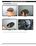
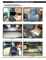
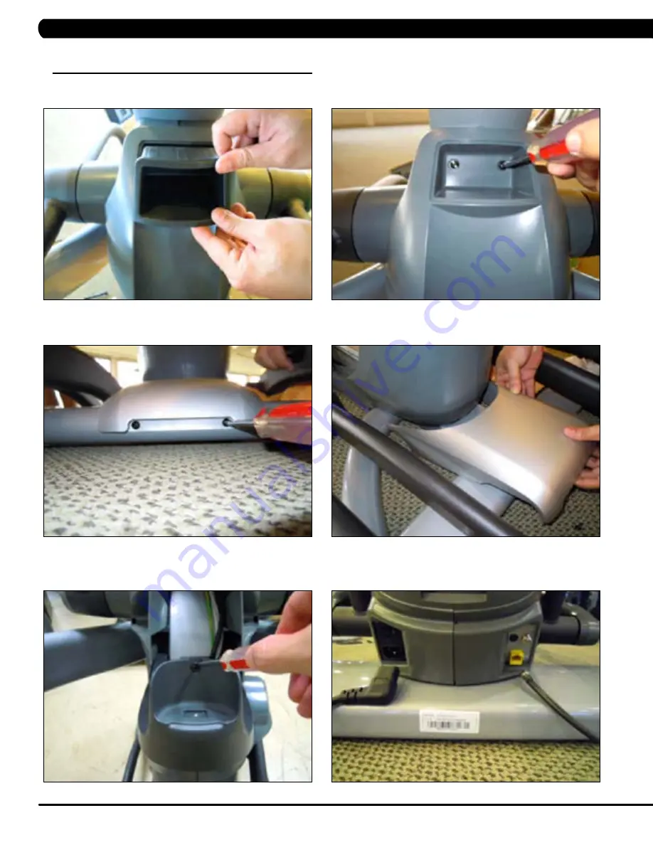
7) Pull out the rubber tray from the cup holder plastic (figure G).
8) Remove the 2 screws to disassemble the cup holder plastic and remove it from the unit (Figure H).
9) Remove the 2 screws to disassemble and remove the middle stabilizer sweat cover (Figures I & J).
10) Remove the 1 screw (exposed when the cup holder is removed) holding the orange slot cover to the frame and remove it (Figure K).
11) Remove all of the cables from the front shrouds (Figure L).
figuRE l
figuRE J
figuRE H
figuRE k
figuRE i
figuRE g
cHaptER 9: paRt REplacEMEnt guidE
Содержание E5X-04
Страница 4: ...1 1 1 SERIAL NUMBER LOCATION SERIAL Number LOCATION CHAPTER 1 Serial Number Location...
Страница 18: ...15 8 1 Electrical DiagramS CHAPTER 8 Troubleshooting HURES5x C Electrical block diagram...
Страница 19: ...16 8 1 electrical diagramS CONTINUED Pulse Sensor Wire Chapter 8 Troubleshooting...
Страница 21: ...18 POWER RESISTANCE WIRE ECB Wire 8 1 electrical diagramS Continued CHAPTER 8 Troubleshooting...
Страница 24: ...21 8 4 LCB1_ErP wiring connection CHAPTER 8 Troubleshooting...
Страница 84: ...81 notes...

