background image

20

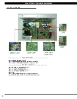
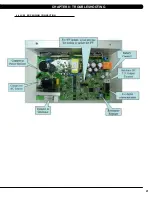
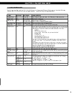
8.3 lcb lEd indicatoRS

cHaptER 8: tRoublESHooting

====================== fiRMwaRE dEfinition ========================

lEd6: lcb StatuS (blinking: ok)

lEd7: RESiStancE REgulatE StatuS (bRigHt : noRMal )

lEd8: ucb/lcb coMMunication StatuS (blinking : ok )

====================== HaRdwaRE dEfinition =======================

lEd1: ac plug-in StatuS (bRigHt : ac )

lEd2: dc 5V StatuS (bRigHt : ok)

lEd3: ac plug-in StatuS (bRigHt : ac )

lEd4: dc 12V StatuS (bRigHt : ok )

lEd5: RpM

lEd9: ucb powER Supply StatuS (bRigHt: powER on)

lEd10: RESiStancE pwM StatuS (bRigHt: RESiStancE on)

Содержание E5X-04

Страница 1: ...E 5 x 0 3 S u s p e n s i o n e l l i p t i c a l S E R V IC E M ANUA l E 5 X 0 4 S U S P E N S ION E LLIPTICAL S E R V IC E M ANUA l...

Страница 2: ...gineering mode 6 1 Engineering Mode Overview 13 CHAPTER 7 SERVICE MODE 7 1 Service Mode Overview 14 CHAPTER 8 TROUBLESHOOTING 8 1 Electrical Diagram 15 8 2 Error Codes on the Console 19 8 3 LCB LED In...

Страница 3: ...rtical Stabilizer Arm Replacement 56 9 19 Incline Arm Cover Replacement 57 9 20 Handlebar Service 58 9 21 Testing the Suspension Elliptical 59 CHAPTER 10 Suspension Elliptical SPECIFICATIONS AND ASSEM...

Страница 4: ...1 1 1 SERIAL NUMBER LOCATION SERIAL Number LOCATION CHAPTER 1 Serial Number Location...

Страница 5: ...2 console serial number location 1 1 SERIAL NUMBER LOCATION CONTINUED Chapter 1 Serial Number Location SN PLACEMENT...

Страница 6: ...o not carry this unit by it s supply cord or use the cord as a handle Close supervision is necessary when the Suspension Elliptical is used by or near children or disable persons Do not use outdoors D...

Страница 7: ...ension Ellipticals into should not have anything else running on that same circuit besides other Suspension Ellipticals up to 3 per 15 amp circuit and 4 per 20 amp circuit The easiest way to verify th...

Страница 8: ...y 100 lint free cloth and water soap mixture wipe down the entire console area including the hand grips and hand rails MONTHLY 1 Vacuum under and around the Elliptical Trainer If you need to move it u...

Страница 9: ...t Team identifies items that require specific attention the latest version will always be available on the Matrix website www matrixfitness com DAILY MAINTENANCE ITEMS 1 Attempt to wobble the unit bac...

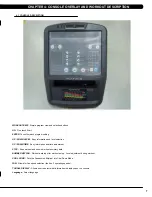
Страница 10: ...workout and shows workout summary data NUMBER KEYPAD Workout data input for workout setup Level adjustment during workout COOL DOWN Puts the Suspension Elliptical into Cool Down Mode FAN Allows for fa...

Страница 11: ...display will read 3 2 1 Begin and then the program will start 4 3 workout setup steps fat burn ROLLING HILLS The Rolling Hills program is a level based program that automatically adjusts the resistan...

Страница 12: ...the next level The test could take upwards of 30 minutes for very fit individuals Once the test ends a recovery period cool down will begin and the user s results are calculated and displayed Results...

Страница 13: ...ng You can grab these sensors in any program to view your current heart rate 1 Start pedaling and press the HEART RATE key Then press ENTER 2 Select Age by using the UP or DOWN LEVEL keys and press SE...

Страница 14: ...s in Manager Mode use the UP and DOWN LEVEL keys Each of the custom settings will show on the display 3 To select a custom setting press the ENTER key when the desired setting is shown 4 To change the...

Страница 15: ...t used for program calorie expenditure calculations Accumulated Distance N A 0 99 999 Miles Total distance for all programs Accumulated Time N A 0 999 999 hours Total time for all programs displayed i...

Страница 16: ...year 11 12 MM is the month e g 08 09 10 nnnnn is the actual serial number Use the UP DOWN LEVEL keys to navigate the layers and the number keys to input the serial number The product name is dependent...

Страница 17: ...ally sets the Accumulated Distance and Time Service 4 CSafe RF Test Press the ENTER key to test CSAFE Press the ENTER key again to test the RF Service 5 Error Log Shows the last 10 errors Press and LE...

Страница 18: ...15 8 1 Electrical DiagramS CHAPTER 8 Troubleshooting HURES5x C Electrical block diagram...

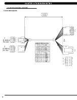
Страница 19: ...16 8 1 electrical diagramS CONTINUED Pulse Sensor Wire Chapter 8 Troubleshooting...

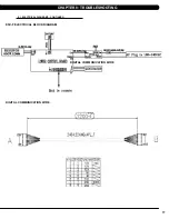
Страница 20: ...17 8 1 electrical diagramS Continued CHAPTER 8 Troubleshooting Digital Communication Wire Digital Communication Wire E5x F Electrical block diagram...

Страница 21: ...18 POWER RESISTANCE WIRE ECB Wire 8 1 electrical diagramS Continued CHAPTER 8 Troubleshooting...

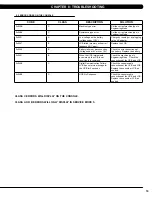
Страница 22: ...or over 15V Check the wire connections at the battery Replace the battery 0x0441 b When the UCB implements a command the LCB is not receiving this command Check the machine type in Engineering Mode Ch...

Страница 23: ...ulate Status bright Normal LED8 UCB LCB Communication Status blinking OK Hardware definition LED1 AC plug in Status bright AC LED2 DC 5V Status bright OK LED3 AC plug in Status bright AC LED4 DC 12V S...

Страница 24: ...21 8 4 LCB1_ErP wiring connection CHAPTER 8 Troubleshooting...

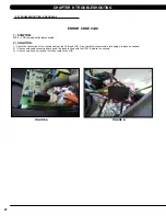
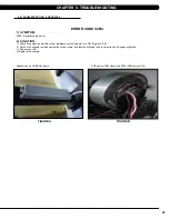
Страница 25: ...ommunication disconnected 2 SOLUTION 1 Check the connection of the console cable at the UCB and LCB Also check the console cable for damage replace as needed 2 If the console cable connections are goo...

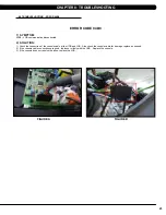
Страница 26: ...ommunication disconnected 2 SOLUTION 1 Check the connection of the console cable at the UCB and LCB Also check the console cable for damage replace as needed 2 If the console cable connections are goo...

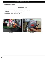
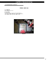
Страница 27: ...tery disconnection or fail When the power is on LCB battery voltage is less than 6 VAC 2 SOLUTION 1 Check the battery wire connection between the battery and LCB Figure A 2 Check the battery voltage F...

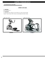
Страница 28: ...r use on HUREA5x frame ERROR CODE 02B4 1 SYMPTOM 02B4 Resistance type error 2 SOLUTION 1 Check if the machine has the correct resistance system resistor or ECB Figures A B 2 Check if the console is ma...

Страница 29: ...ine type is E5x 02 Machine type is E5x 03 ERROR CODE 02AB 1 SYMPTOM 02AB Machine type error 2 SOLUTION 1 Check if the console machine type is matched with the correct frame in Engineering Mode Remarks...

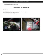
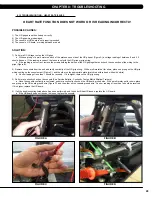
Страница 30: ...AC Figure A ERROR CODE 01AC 1 SYMPTOM 01AC Resistance over current 2 SOLUTION 1 Check the resistance coming out of the resistor Figure A If the resistance value is under 8 ohms replace the power resis...

Страница 31: ...TROUBLESHOOTING 1 SYMPTOM No resistance 2 SOLUTION 1 Check the power resistance wire connection between the power resistor and LCB Figure A 2 Check the resistance coming out of the resistor Figure A I...

Страница 32: ...from the unit and verify continuity of the HR grip wiring With a multi meter set for ohms place one prong on the HR grip wiring coming up the console mast Figure C and the other on the appropriate pla...

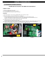
Страница 33: ...ess room power b If LED9 is still not lit check the incoming AC power to the LCB If the incoming power is not correct replace the power cord c Replace the LCB if all power components are OK and there...

Страница 34: ...ER c Test the affected keypad If the keypad works in the keypad test it may not be a functioning key in the program used for testing it 2 Check the connections of the keypad at the UCB a Remove the co...

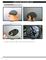
Страница 35: ...ckwise Figures A B 2 Remove the 3 screws holding the disk to the axle Figure C 3 Remove the disk Figure D 4 Reverse Steps 1 3 to install a new disk NOTE The 3 screws removed in Step 2 should be torque...

Страница 36: ...cure the handlebar so that it is out of the way Figure D 4 Remove the front disks as outlined in Section 9 1 5 Detach the pedal arm from the crank bearing assembly Figure E 6 Remove the 2 screws that...

Страница 37: ...the unit Figure H 9 Remove the 2 screws to disassemble and remove the middle stabilizer sweat cover Figures I J 10 Remove the 1 screw exposed when the cup holder is removed holding the orange slot cov...

Страница 38: ...other Figure M 13 Turn the crank to the slotted portion of the shroud Figure N 14 Remove the front shrouds for frame access Figures O P 15 Reverse Steps 1 14 to install new shrouds NOTE The bolt nut...

Страница 39: ...disks from the machine as outlined in Section 9 1 3 Disconnect all wires from the LCB Figure A 4 Remove the 2 screws holding the LCB to the frame Figure B 5 Reverse Steps 1 4 to install a new LCB 6 Te...

Страница 40: ...ront shrouds as outlined in Section 9 2 4 Cut the cable tie holding the cable to the frame Figure A 5 Unplug the power cable connector of the generator Figure B 6 Loosen the nut holding the generator...

Страница 41: ...tor belt Figure F 10 Remove the generator from the frame 11 Reverse Steps 1 10 to install a new generator Re install the belts as outlined in Section 9 5 NOTE The 3 screws removed in Step 7 should be...

Страница 42: ...ned in Section 9 4 5 To install a new belt first put the belt installation tool on the pulley Figure A 6 Put the new belt on the installation tool Figure B 7 Turn the pulley until the belt is installe...

Страница 43: ...e pulley counter clockwise until there is enough slack in the belt to remove it Figures A B 4 Install the replacement belt and reverse necessary steps to secure the assembly until the belt is tight NO...

Страница 44: ...e Figure B 5 On the left side of the frame remove the retaining ring that holds the pulley axle bearing into the frame Figure C 6 Remove the pulley axle set assembly from the frame Clean any debris fr...

Страница 45: ...f the frame remove the retainer clip that holds the drive axle bearings in the frame Figure A 5 Install an M10 screw into the drive axle Figure B 6 Turn the screw until the head is close to the drive...

Страница 46: ...igure I 13 Mount the other tool from Figure H behind the bearing cap portion of the tool Use the M10 x 65L screw with a washer and a nut to attach the tool to the drive axle Figure J 14 Turn the screw...

Страница 47: ...asher and a nut to attach the tool to the drive axle Figure O 19 Turn the screw at least 4 full revolutions into the drive axle Then turn the nut until it is close to the cup portion of the tool Figur...

Страница 48: ...Use a screwdriver to remove the iron plate from the drive axle Figures S T 23 Re install the belts as outlined in Sections 9 5 and 9 6 24 Test the Suspension Elliptical as outlined in Section 9 21 fig...

Страница 49: ...w should be at least 40 long into the crank hole Then turn the screw until the crank can be separated from the axle Figure B 5 Install the replacement crank There should be a 4mm gap between the end o...

Страница 50: ...screws that hold the mounting plate to the console Figure C 5 Attach the mounting plate to the new console 6 Connect the wire connections to the new console 7 Carefully push the wires into the consol...

Страница 51: ...connect the cord from the machine 2 Remove the console as outlined in Section 9 10 3 Remove the back cover of the console Figure A 4 Unplug and remove the faulty overlay Figure B 5 Clean the console a...

Страница 52: ...Figure G 10 Press down on the corners of the overlay to keep it in place then remove the protective film Figure H I 11 Once the overlay is in the correct position press down on the overlay with a clot...

Страница 53: ...fully remove the wires from inside the console mast until the connectors on the ends come free and disconnect Figure C 5 To install a new handlebar assembly connect the new handlebar and carefully pus...

Страница 54: ...bolts that hold on the pivot cap and remove the cap Figure C 4 Unplug and separate the heart rate connector exposed once the pivot cap is removed Then remove the 4 screws that hold the dual action ha...

Страница 55: ...that hold the plastic pedal to the foot plate Figure B 3 Remove the plastic foot pedal Figure C 4 Clean the foot plate to remove any rubber or debris 5 Reverse Steps 1 4 to install a new foot pedal 6...

Страница 56: ...her Figure D 5 The swing arm can now be separate from the pedal arm Figure E 6 Remove the bolt that holds the link arm to the pedal arm and remove the pedal arm Figure F 7 Reverse Steps 1 5 to install...

Страница 57: ...ushings where the dual action handlebar meets the link arm Figure B 3 Remove the bolt that holds the link arm to the pedal arm and remove the link arm Figure C 4 Reverse Steps 1 3 to install a new lin...

Страница 58: ...turn it into the shaft Figure D 5 Use a mallet to hit the head of the bolt until the swing arm can be separate from the pedal arm and remove the pedal arm Figures E F 6 Reverse Steps 1 5 to install a...

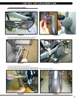
Страница 59: ...r pivot joint of the vertical stabilizer arm Figure C 3 Remove the vertical stabilizer arm Figure D 4 Reverse Steps 1 3 to install a vertical stabilizer arm NOTE Tighten the bolt removed in Step 2 to...

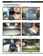
Страница 60: ...LACEMENT 1 Remove the screw that holds the plastic cover on the arm Figures A B 2 Remove the incline arm cover Figure C 3 Reverse Steps 1 2 to install a new incline arm figure C figure B figure a Chap...

Страница 61: ...screwdriver from the underside of the bar 2 Once the screws are removed lift the part carefully then disconnect any wire connections to fully remove the part This includes the resistance buttons and h...

Страница 62: ...anual for procedure 3 Without hitting start or entering any exercise modes stand on the machine and hold the handlebars while initiating movement to simulate exercising While moving listen for any odd...

Страница 63: ...k TIME ELAPSED TIME REMAINING TOTAL PROGRAM TIME CLOCK DISTANCE KILOMETERS OR MILES CALORIES SPEED LEVEL RPM HEART RATE METS WATTS STATIC PROFILE DISPLAY User defined multi language display Yes Englis...

Страница 64: ...0 8P x 10L Yellow 2 Screw M5 x 0 8 x 12L Black 2 bags 4 Spring Washer 8 2 x 15 4 x 2 0t black 2 bags 4 Socket head cap screw M8 x 1 25P x 20L 10 9 grade minimum Black 2 bags 1 socket head cap screw m8...

Страница 65: ...62 10 3 SUSPENSION ELLIPTICAL ASSEMBLY STEPS step 1 CHAPTER 10 SUSPENSION ELLIPTICAL SPECIFICATIONS AND ASSEMBLY GUIDE...

Страница 66: ...63 10 3 Suspension Elliptical assembly steps continued step 2 RED HARDWARE BAG CHAPTER 10 SUSPENSION ELLIPTICAL SPECIFICATIONS AND ASSEMBLY GUIDE...

Страница 67: ...64 10 3 SUSPENSION ELLIPTICAL ASSEMBLY STEPS CONTINUED step 3 Pink hardware bag CHAPTER 10 SUSPENSION ELLIPTICAL SPECIFICATIONS AND ASSEMBLY GUIDE...

Страница 68: ...65 10 3 Suspension Elliptical assembly steps continued Torque this bolt to 80 N m step 4 Green Yellow HARDWARE BAG CHAPTER 10 SUSPENSION ELLIPTICAL SPECIFICATIONS AND ASSEMBLY GUIDE...

Страница 69: ...66 10 3 SUSPENSION ELLIPTICAL ASSEMBLY STEPS CONTINUED step 5 Red hardware bag CHAPTER 10 SUSPENSION ELLIPTICAL SPECIFICATIONS AND ASSEMBLY GUIDE...

Страница 70: ...67 10 3 Suspension Elliptical assembly steps continued step 6 CHAPTER 10 SUSPENSION ELLIPTICAL SPECIFICATIONS AND ASSEMBLY GUIDE...

Страница 71: ...68 10 3 SUSPENSION ELLIPTICAL ASSEMBLY STEPS CONTINUED step 7 Blue Black hardware bag CHAPTER 10 SUSPENSION ELLIPTICAL SPECIFICATIONS AND ASSEMBLY GUIDE...

Страница 72: ...69 10 3 Suspension Elliptical assembly steps continued step 8 White hardware Bag CHAPTER 10 SUSPENSION ELLIPTICAL SPECIFICATIONS AND ASSEMBLY GUIDE...

Страница 73: ...70 10 3 SUSPENSION ELLIPTICAL ASSEMBLY STEPS CONTINUED step 9 pink hardware bag CHAPTER 10 SUSPENSION ELLIPTICAL SPECIFICATIONS AND ASSEMBLY GUIDE...

Страница 74: ...71 10 3 Suspension Elliptical assembly steps continued step 10 pink hardware Bag CHAPTER 10 SUSPENSION ELLIPTICAL SPECIFICATIONS AND ASSEMBLY GUIDE...

Страница 75: ...72 10 3 SUSPENSION ELLIPTICAL ASSEMBLY STEPS CONTINUED step 11 pink hardware bag CHAPTER 10 SUSPENSION ELLIPTICAL SPECIFICATIONS AND ASSEMBLY GUIDE...

Страница 76: ...73 10 3 Suspension Elliptical assembly steps continued step 12 pink hardware Bag CHAPTER 10 SUSPENSION ELLIPTICAL SPECIFICATIONS AND ASSEMBLY GUIDE...

Страница 77: ...l for optimum use Once you have placed your unit where you intend to use it raise or lower one or both of the adjustable levelers located on the bottom of the frame Use a 6mm Allen wrench through the...

Страница 78: ...s outlined in Section 9 1 2 Remove the 6 screws holding the console front to the back and split the console Figures A B 3 Remove the 2 screws holding on the blank headphone jack plastic to the console...

Страница 79: ...f installing a MYE TV the PCTV does not use the entertainment overlay 8 Remove the existing heart rate overlay from the lower portion of the console Figure I 9 Clean the console area with alcohol to r...

Страница 80: ...4 pin black connector to the power wire coming up the console mast from the base of the unit 16 Plug the side of the controller wire labeled To Console into the CSafe board mounted on the console back...

Страница 81: ...2 screws Figure U The small cover with the Matrix logo that makes up the top of the rear console cover is no longer used with a TV bracket 20 Mount the console back onto the unit making sure to make a...

Страница 82: ...the TV bracket being sure to tuck the tabs of the plate installed during Step 20 into the console plastic Figure BB 28 Mount the TV to the TV bracket using 4 screws sent with the TV Figure CC 29 Put t...

Страница 83: ...the software files into the UCB folder on the USB flash drive the access should read MATRIX FW UCB Figure B 3 Insert the USB flash drive into the USB port on the console Figure C 4 With the display is...

Страница 84: ...81 notes...
Страница 85: ...MATrix Fitness systems corp 1610 Landmark Drive Cottage Grove wi 53527 USA TOLL FREE 866 693 4863 www matrixfitness com FAX 608 839 1717 REV 01 KO...

Отзывы: