35
9.2 fRont SHRoud REplacEMEnt - continuEd
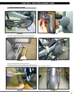
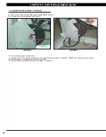
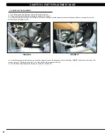
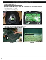
12) Remove the 9 screws to detach the front shrouds from the frame (or each other) (Figure M).
13) Turn the crank to the slotted portion of the shroud (Figure N).
14) Remove the front shrouds for frame access (Figures O & P).
15) Reverse Steps 1-14 to install new shrouds.
note:
The bolt / nut removed in Step 5 should be torqued to 70 N-m.
figuRE p
figuRE n
figuRE o
figuRE M
cHaptER 9: paRt REplacEMEnt guidE
Содержание E5X-04
Страница 4: ...1 1 1 SERIAL NUMBER LOCATION SERIAL Number LOCATION CHAPTER 1 Serial Number Location...
Страница 18: ...15 8 1 Electrical DiagramS CHAPTER 8 Troubleshooting HURES5x C Electrical block diagram...
Страница 19: ...16 8 1 electrical diagramS CONTINUED Pulse Sensor Wire Chapter 8 Troubleshooting...
Страница 21: ...18 POWER RESISTANCE WIRE ECB Wire 8 1 electrical diagramS Continued CHAPTER 8 Troubleshooting...
Страница 24: ...21 8 4 LCB1_ErP wiring connection CHAPTER 8 Troubleshooting...
Страница 84: ...81 notes...

