Page 47
mPower 300 Series (Rev G)
5.9 Parallel Operation in Share Bus Mode
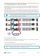
Multiple units of same model number can be connected in parallel in order to create a system with higher total current
and thus higher power. To achieve that, the units have to be connected with their DC outputs and their Share Bus. The
Share Bus will balance the units in their internal voltage regulation and thus current regulation, which will result in a
balanced load distribution.
In the parallel operation, a specific unit, a Share Bus master, has to be picked as the leading unit which drives the Share
Bus slaves. The master unit will remain fully controllable, also via analog or digital interface. The slaves, however, are
restricted regarding set value adjustment. Their set values are just limits for the units, while control is via the Share Bus. A
slave unit still can be controlled remotely, but not like a master unit. All slaves can be monitored by any of the interfaces.
The Share Bus controls the process variable U (voltage) only. This means the DC outputs of slave
units have to be switched on or off either manually or remotely, which is very easy in analog remote
control using pins REM-SB connected in parallel as well.
Share
Sense
NC NC
+ -
-
+
Analog Interface
USB
LAN
Output
Power Input
Share
Sense
NC NC
+ -
-
+
Analog Interface
USB
LAN
Output
Power Input
Share
Sense
NC NC
+ -
-
+
Analog Interface
USB
LAN
Output
Power Input
Load
Parallel
On/Off
5.9.2.1 Wiring the DC outputs
The DC output of every unit in the parallel operation is simply connected to the next unit using cables with cross section
according to the maximum current and with short as possible length.
5.9.2.2 Wiring the Share bus
The Share bus is wired from unit to unit ideally with an twisted pair of cables with non-critical cross section. We
recommend to use 0.5 mm² to 1.0 mm². A maximum of 10 units can be connected via Share bus.
The Share bus is poled. Take care for correct polarity of the wiring!

