background image

5

Overview / Replacement Parts

Congratulations on your purchase of the MARUS Track Light! You have chosen a product that will provide 

years of reliable, trouble-free service. 

This manual contains instructions for installing, maintaining, and operating the TL 500 model Track light. Fol-

lowing these instructions will ensure smooth operation and a long life for your equipment.

The TL 500 Track Light features include:


•  A sleek asepsis design that promotes simple, thorough cleaning.


•  Ergonomic handles that reduce stress on wrists and hands.


•  A light head that includes a third-axis positional adjustment for precise alignment with the oral cavity.


•  Single-button shield removal and an easy to replace bulb that reduces costly service  


   calls.


•  Smooth and quiet gliding track movement with optional trolley brake.


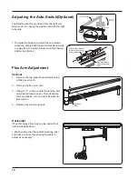
•  An optional, adjustable auto-switch that automatically turns the light on when the flex  


   arm is lowered.

Serial / Model

Number

Set Screw

022R006

Trolley Assembly

52R304

Bushing Retainer

52R255

Reflector

22186

Yoke Pivot Cap

20317

Bulb

30441

Reflector Shield

20289

Front End Cap

52R110

Содержание TL 500

Страница 1: ...TL 500 Track Light Owner s Manual Marus 11727 Fruehauf Drive Charlotte NC 28273 USA Technical Support 800 304 5332 FAX 888 861 9366...

Страница 2: ...We will pay the return freight charges from the factory to the dealer This guarantee does not cover dam age resulting from improper installation misuse or accidents incurred in shipping and handling...

Страница 3: ...quirements 10 Installation Instructions 10 Adjusting the Light head s Horizontal Rotation 13 Adjusting the Light head s Vertical Rotation 13 Adjusting the Light head s Third Axis Rotation 14 Focusing...

Страница 4: ...escriptions calibration instructions or other information that will assist technical personnel to repair and replace serviceable items Product Identification This dental light can be identified by its...

Страница 5: ...10 to 90 Relative Humidity The pre installation must be performed according to the requirements in our Pre installation Instructions As manufacturers of electro medical products we can assume respons...

Страница 6: ...FUSE 2 AMP 3 AG 230V Electrical Specifications IEC Medical Device Classification Classification 1 Type B Operation Mode Intermittent Splash Protection IPX4 Volts Cycles Amps Dental light 115 VAC 60 HZ...

Страница 7: ...promotes simple thorough cleaning Ergonomic handles that reduce stress on wrists and hands A light head that includes a third axis positional adjustment for precise alignment with the oral cavity Sin...

Страница 8: ...6 Suggested Mounting Methods Stub out wiring at this point 1 1 4 access hole in mounting pallet 64 35 1 2 33 5 8 Chair Centerline 42 min Recommended Ceiling joists 6 3 3 8 0 min 12 0 max...

Страница 9: ...eiling BE SURE TO BRACE STRUCTURE IN BOTH DIRECTIONS MINIMUM SIZE 3 4 PLYWOOD PANEL 77 5 8 x 10 WIDE CEILING JOISTS 16 ON CENTER LAG BOLTS NOT INCLUDED LONG ENOUGH TO GO AT LEAST 3 4 INTO PLYWOOD PANE...

Страница 10: ...TRACK PALLET SUSPENDED CEILING PREFORMED BRACKETS PLYWOOD PALLET 77 5 8 10 1 1 2 DIA HOLE 1 1 2 x 3 4 x 1 8 CHANNELS PREFORMED AND BOLTED TO PLYWOOD PALLET Suggestions for Suspended Ceiling continued...

Страница 11: ...LOCATED IN TRACK Mounting Parallel and Perpendicular Mounting parallel to ceiling joist on new construction Mounting parallel to ceiling joist on existing construction Mounting perpendicular to ceilin...

Страница 12: ...ach end of the track remove the transformer cover and remove the side trim panels The side trim panels are removed by pulling straight outward after the end caps are removed See figure below 2 Use 5 1...

Страница 13: ...unter clockwise until it unscrews from the track Slide the trolley onto the track being sure that the wheels that are concave align with the raised side of the track 7 Plug the power cable into the tr...

Страница 14: ...ange position according to whether the opera tor is right or left handed THIS SCREW MUST BE USED IN EITHER ONE OF THE TWO LO CATIONS MALFUNCTION AND OR DAMAGE MAY RESULT TO THE LIGHT IF THIS SCREW IS...

Страница 15: ...e adjustment on each side to achieve even friction To correct a stiff or loose movement Adjusting the Light head s Horizontal Rotation 1 Remove the plug located at the rear of the pivot housing 2 Inse...

Страница 16: ...et of cardboard position ing the bulb shield 27 inches away 2 Turn the light on 3 Using the knob at the back of the light adjust the focus to obtain the sharpest light pattern Pivot nut Back cover Foc...

Страница 17: ...e align the pins with the matching holes and press the bulb firmly into place 4 Wipe the glass portion of the bulb clean with denatured alcohol 5 Close the shield by depressing the shield release butt...

Страница 18: ...a 5 64 hex wrench 2 Remove the flex arm cover 3 Using a 1 2 wrench adjust the tension bolt until desired tension is set Turn clockwise for more tension turn counter clockwise for less tension 4 Repla...

Страница 19: ...r than recommended dilution ratios Only disinfect by wiping no spray disinfection Please be aware that the manufacturer expressly rejects any claims for warranty or damages when using other cleaning a...

Страница 20: ...ed Surfaces The painted surfaces of your light can be cleaned by simply wiping with a damp cloth No other protective coating is required to preserve the permanent luster of the painted surface CAUTION...

Страница 21: ...19 Dimensions and Range of Motion TL 500 Track Light 58 25 14 75 28 75 10 5 79 54 288...

Страница 22: ...0 Dimensions and Range of Motion TL 500 Track Light 16 5 15 42 270 12 39 DIMENSION VARIES DEPENDING UPON CEILING HEIGHT SEE DCI EQUIPMENT CATALOG FOR CHART REGARDING TRACK LIGHT SUSPENSION TUBE LENGTH...

Страница 23: ...nsions and Range of Motion Light Head Service Location Track Light Power Supply 120 120 40 140 Transformer Cover 6 32 Phillips Head Screw Transformer Insulator Transformer Fuses Ground Location Power...

Страница 24: ...22 Service Location Light Head Bulb Replacement ON OFF Toggle Switch...

Страница 25: ...1 BLACK 2 WHITE 3 GREEN 4 RED RED GRN BLK WHT RED GRN BLK WHT 1 2 3 WHT WHT LAMP INTENSITY SWITCH WHT DENT AL LIGHT BLK CONNECTOR PIN LOCA TION 1 2 3 4 RED GRN BLK WHT RED YEL BLK WHT ARM SWITCH 1 BL...

Страница 26: ...T 1 BLACK 2 WHITE 3 GREEN 4 RED RED GRN BLK WHT RED GRN BLK WHT 1 2 3 WHT WHT LAMP INTENSITY SWITCH WHT DENTAL LIGHT BLK CONNECTOR PIN LOCATION 1 2 3 4 RED GRN BLK WHT RED YEL GRN BLK WHT ARM SWITCH 1...

Страница 27: ...age to the light MEDICAL ELECTRICAL EQUIPMENT ELECTROMAGNETIC COMPATIBILITY TECHNICAL DESCRIPTION ELECTROMAGNETIC COMPATIBILITY testing has been done for this product ACCESSORY USE Using accessory dev...

Страница 28: ...No I O lines Mains power quality should be that of typical commercial or hospital environment SURGE IEC 61000 4 5 1 kV differential mode 2 kV common mode 1 kV differential mode 2 kV common mode Mains...

Страница 29: ...is product is intended for use in the electromagnetic environment specified below The customer or the user of this product should assure that it is used in such an environment Guidance and manufacture...

Страница 30: ...establishments and those directly connected to the public low voltage power supply network that supplies buildings used for domestic purposes RF emissions CISPR 11 RF emissions CISPR 11 Harmonic Emiss...

Страница 31: ...er positions If ceiling mount or track mount check the column at the tripod trolley and arm adapter that the roll pin is installed to prevent the column from unscrewing Check all set screws The light...

Страница 32: ......

Страница 33: ......

Страница 34: ......

Страница 35: ...____________________________________________ ________________________________________________________________ ________________________________________________________________ _________________________...

Страница 36: ...11727 Fruehauf Drive Charlotte NC 28273 USA Technical Support 800 304 5332 FAX 888 861 9366 92353 Rev 5 02 12...

Отзывы: