


12
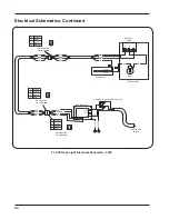
Installation Instructions -
continued...
10. Re-install the side trim extrusions, transformer cover, and end caps removed in step #1.
11. Place the locking tab retaining collar on the post just above the locking tab slot and lightly tighten the set
screw.
CAUTION: OVERTIGHTENING THE SETSCREW WILL MAR THE PAINTED SURFACE.
16. This completes the installation of the TL 500 Track Light Assembly. Turn on the light and check for proper
operation and balance. The light head is fully assembled and functionally tested prior to leaving the fac
-
tory. Should adjustments need to be made, please refer to the Adjustments section of this manual.
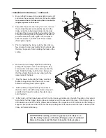
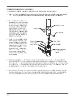
Setscrews
Light Adapter
Optional Placement
for Left Handed
Position
Locking Tab
Retaining Collar
Rotation Stop
Screw - Right
Hand Position
Power Plugs
13. The rotational stop screw is pre-
installed from the factory, but may
be necessary to change position
according to whether the opera-
tor is right or left handed. THIS
SCREW MUST BE USED IN
EITHER ONE OF THE TWO LO-
CATIONS. MALFUNCTION AND/
OR DAMAGE MAY RESULT TO
THE LIGHT IF THIS SCREW IS
REMOVED ENTIRELY.
14. Grease the light adapter and the
inside of the bottom of the post.
Have an assistant hold the light
assembly with the adapter near
the bottom of the post. Plug the
short male cord into the female
coiled cord firmly being certain
that this plug makes a tight con-
nection so as not to become
disconnected in the future. (See
figure at right).
15. Slide the light adapter into the bottom of the post until it bottoms. Look into the slot to be sure the stop
screw is not within the confines of the slot. Now place the locking tab into the slot in the side of the post.
The locking tab fits flush into the ceiling post. Now loosen the setscrew and the locking tab retaining collar
and lower it over the slot. Align the collar with the bottom of the post and tighten the setscrew firmly. The
assistant supporting the light can now release it. (See figure above).
Содержание TL 500
Страница 21: ...19 Dimensions and Range of Motion TL 500 Track Light 58 25 14 75 28 75 10 5 79 54 288...
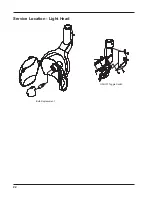
Страница 24: ...22 Service Location Light Head Bulb Replacement ON OFF Toggle Switch...
Страница 32: ......
Страница 33: ......
Страница 34: ......
Страница 36: ...11727 Fruehauf Drive Charlotte NC 28273 USA Technical Support 800 304 5332 FAX 888 861 9366 92353 Rev 5 02 12...