14
M&R Companies 440 Medinah Rd. Roselle, IL 60172 USA
Tel: +630-858-6101 Fax: +630-858-6134
V.120617
5. Operation
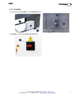
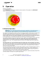
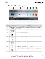
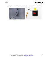
Emergency Stop Button
The red
EMERGENCY STOP
Button is provided to stop all operation of the equipment in an
EMERGENCY
situation. Push the button to activate.
5.1 Machine Operation
IMPORTANT
: The computer Operating System should not be upgraded as it may interfere with the i-
Image S programs.
Any
auto updates can crash the software and any unsaved data will be lost.
The i-Image S is an ink jet printer designed to print a UV blocking dye directly onto the surface of a coated screen,
eliminating the need for film positives. An artist will use ColorPRINT to RIP (or Process) art files. RIP is an
acronym for Raster Image Processor which breaks down art files so the information can be sent and read by the
printer. The files can be sent to the i-Image S workstation via an internal server network (recommended method)
or hand held flash drive. The operator then prints the files directly onto the coated screen surface.
The operating principles of the machine are fairly simple. Ink is supplied to the Printheads using fluid pumps that
draw ink from the main tank located in the base of the machine filling a small sub-tank located inside the
Printhead assembly. The sub-tank has a positive and negative air regulating system that balances the ink
pressure when not in use. This air regulating system is the source of the clicking valves that are heard during
operation.
When the machine is not in use the Printheads will go into a standby mode, known as "Capping." This ensures
the Printhead nozzles stay clean and clear from debris and contaminants. We recommended leaving the machine
powered "ON" during the workweek, even overnight, and fully shut down only for extended periods of five or more
days. This increases the longevity of the valves and ink delivery system. See complete Startup and Shutdown
procedures in this manual for details.
The main components of the i-Image S is the Print Gantry assembly on which the Printhead assembly travels (X-
Axis) and the screen table assembly on which the screen frame is loaded (Y-axis). These components are
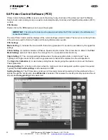
controlled by software known as Printer Control Software (PCS). PCS is the interface used by the operator to
control printer functions, such as print modes, cleaning modes and calibrations.
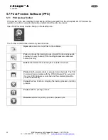
Along with the PCS Software, there is Print Preview Software (PPS) which is used by the operator to import files
and confirm details of each job and color plate being processed.
Содержание i-Image S
Страница 1: ...i Image S Bv2 Part MAN i Image S V 120617...
Страница 2: ......


