○
R
○
Y
○
G
○
O
○
B
TERMINAL
STRIP
○
C
○
R
○
G
○
O
○
Sy
○
1
○
Y
○
L
○
Sc
○
2
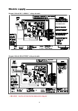
Electric
supply
5
Diagram
1:
Manual
changeover
thermostat
Diagram
2: Automatic
changeover
with
night
setback
Diagram
3:
Automatic
changeover
thermostat with
night
setback/setup
and
override
Electrical
Electrical
Electrical
Electrical
Service
Service
Service
Service
and
and
and
and
Fusing
Fusing
Fusing
Fusing
Warning:
To
avoid
severe
electrical
shock,
turn
off
power
before
servicing
controls
.
Unit
must
be
installed
in
compliance
with
NEC
and
local
codes.
Route
power
wires
through
a
properly sized disconnect switch.
Consult
the
wiring
diagrams
in
this
manual
and
inside
the
cover
of
the
electrical
box
to
complete
the
connection.
See
nameplate
for
proper
fuse
sizing,
minimum
circuit
ampacity
and
voltage
requirements.
If
an
auxiliary
electrical
heater
is
used,
it
must
be
installed
with
a
power
supply
separate
from
the
heat
pump.
Control
Control
Control
Control
W
W
W
Wiring
iring
iring
iring
See
Diagrams
1
through
4
All
heat
pump
functions
are
controlled
by
remote
thermostat
and
must
be
wired
as
shown,
using
approved
copper
wire.
Auxiliary Dry Contact (N.C.)
Common for Night Setback/Setup and Emergency Shutdown Input Signals (—)


