9
1
10
2
11
3
12
4
13
5
14
6
15
7
16
8
11
Microprocessor
control
For
a
complete
description
of
the
operation
of
the
Microprocessor
Control,
see
Operating
Manual
D-5.
Basic
Basic
Basic
Basic
Features
Features
Features
Features
Fan
Fan
Fan
Fan
Speed
Speed
Speed
Speed
Control:
Control:
Control:
Control:
Adjusts
fan
speed
100-80
percent
on
single-circuit
direct-drive
units.
Diagnostic
Diagnostic
Diagnostic
Diagnostic
LEDs:
LEDs:
LEDs:
LEDs:
Red
=
Fault
in
safety
circuit.
Yellow
=
Compressor
on
(not
blinking).
Green
=
Power
on
(24
VAC
is
present
at
board).
Random
Random
Random
Random
Start:
Start:
Start:
Start:
Prevents
power
surges
by
delaying
unit
startup
by
5-35
seconds
so
that
all
units
do
not
start
at
the
same
time.
Occurs
only
when
unit
comes
off
of
either
shutdown,
unoccupied
or
high/low
voltage
modes.
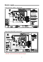
TERMINAL
SIRIP
7
8
13
14
1
12
11
3
10
15
16
5
6
4
9
2
24 VAC (–)
24 VAC
(+) FAN
COMPRESSOR
LOCKOUT ALARM
REVERSING VALVE
A.D. CONTACT (N.O.)
A.D. CONTACT (COM)
※
SEE
※
NOTE
UNOCCUPIED INPUT
NSB / U SIGNAL
EMERGENCY SHUTDOWN
2-HOUR OVERRIDE
DRY CONTACT
ALARM OUTPUT
C
R
G
Y
L
O
Sy
Sc
2
1
4
3
6
5
8
7
MICROPROCESSOR CCG
SEE NOTE 5 CC
ALARM
Testing
Procedure
Procedure
Procedure
Procedure
The
microprocessor
control
board
should
be
tested
while
installed
in
a
unit
with
a
thermostat
attached.
Caution:
Caution:
Caution:
Caution:
When
removing
or
jumping
wires,
be
extremely
careful
not
to
short
the
secondary
side
or
come
in
contact
with
line
voltage.
The
following
procedure
outlines
how
to
test
the
microprocessor
control
board’s
individual
functions
while
installed
in
a
unit.
1.
Move
shunt
#1
to
“test”
position.
2.
Apply
voltage
to
the
unit
assuring
the
microprocessor
control
board
is
accessible
for
troubleshooting.
3.
Take
meter
readings
as
indicated
below.
Fan
Fan
Fan
Fan
Function:
Function:
Function:
Function:
On
a
call
for
fan
operation
.
.
.
“C”
to
“G”
terminals
should
read
24
volts.
“L1”
to
“L2”
line
voltage
should
match
incoming
line
voltage
(208,
220,
230,
265,
380
or
460
volts).
F
FF
Fan
an
an
an
Speed
Speed
Speed
Speed
Control:
Control:
Control:
Control:
On
a
call
for
fan
function
.
.
“FAN”
to
“FAN
COM”
measured
voltage
should
vary
with
adjustment
of
speed
controller
stem.
Compressor:
Compressor:
Compressor:
Compressor:
On
a
call
for
compressor
function
.
.
.
“C”
to
“Y”
terminals
should
read
24
volts.
Contact
terminals
“SY”
to
“SC”
should
read
0
ohms.
Terminals
“SC”
to
#2
should
now
be
open.
Overflow
Overflow
Overflow
Overflow
Detector:
Detector:
Detector:
Detector:
Jumper
from
“SENSOR”
terminal
to
ground
unit
should
lock
out
unit.
“L”
to
“R”
terminals
should
read
24
volts
if
“COM
/
24
VAC”
shunt
is
set
to
“COM”.
Lockout:
Lockout:
Lockout:
Lockout:
Pull
either
wire
HPI,
LPI
or
AUX1
while
unit
is
running.
Unit
should
lock
out.
“L”
to
“R”
terminals
should
read
24
volts
if
“COM
/
24
VAC”
shunt
is
set
to
“COM”.
Return
shunt
#1
to
“RS”
(random
start)
or
“NO
RS”
depending
on
application.
Remove
any
additional
jumpers
and
return
all
wiring
back
to
its
original
configuration.
Condensate
Condensate
Condensate
Condensate
Overflow:
Overflow:
Overflow:
Overflow:
A
sensor
in
the
drain
pan
electrically
senses
the
presence
of
water. Switch
is
tied
to
the
safety
lockout
circuit.
Compressor
Compressor
Compressor
Compressor
Anti
Anti
Anti
Anti----short
short
short
short
Cycle:
Cycle:
Cycle:
Cycle:
A
5-minute
time
delay
prevents
compressor
short
cycling
and
extends
motor
life.
Optional
Optional
Optional
Optional
Field
Field
Field
Field
Adjustments
Adjustments
Adjustments
Adjustments
No
No
No
No
Random
Random
Random
Random
Start:
Start:
Start:
Start:
A
jumper
allows
elimination
of
the
random
start
feature.
TTTTest
est
est
est
Mode:
Mode:
Mode:
Mode:
A
jumper
allows
elimination
of
all
time
delays
to
simplify
unit
checkout
operation
by
qualified
service
personnel
only.
Auto
Auto
Auto
Auto----Reset:
Reset:
Reset:
Reset:
A
jumper
allows
auto-reset
of
the
safety
trip.
The
unit
will
automatically
reset
after
20
minutes.
Fault
Fault
Fault
Fault
Output:
Output:
Output:
Output:
A
terminal
allows
connection
of
an
auto-
changeover
thermostat
with
an
LED.
Signal
may
be
24
VAC
(+)
or
(–).
LED STATUS:
Yellow “On” . . . . . . . . . . . Compressor On
Green “Off” . . . . . . . . . . . No 24 VAC
Green “On” . . . . . . . . . . . 24 VAC Present
Green “1 Flash” . . . . . . . . . Low Voltage
Green “2 Flash” . . . . . . . . . High Voltage
Red “Off” . . . . . . . . . . . . . . No Faults (Normal)
Red “On” . . . . . . . . . . . . . . Emergency Shutdown
Red “1 Flash” . . . . . . . . . . . H.P. Fault
Red “2” Flash” . . . . . . . . . . L.P. Fault
Red “3 Flash” . . . . . . . . . . . W.T. Fault


