8
HydroBank MS Installation and Operation Manual MAMM-WSHP-IOM-1MSA (October 2014)
Horizontal Unit Installation
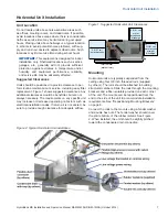
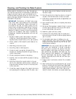
Repositioning Mounting Brackets
Horizontal unit mounting brackets can be repositioned
from the end to the side of the unit as needed to accom-
modate installation requirements, as follows.
1. Raise and support the corner of the unit to provide
access to the mounting bracket.
2. Carefully pry the rubber isolator out of the bracket.
3. The mounting bracket is held in place with two sheet
metal screws and one mounting bolt. Remove all
three fasteners and set aside for reassembly.
4. Move the mounting bracket from the end to the side
of the unit, or vice-versa (see Figure 3).
5. Screw the center mounting bolt into the provided
connector and finger-tighten.
6. Align the mounting bracket with the unit and screw
in the sheet metal screws in the holes provided.
7. Tighten the center mounting bolt to 17 ft-lbs.
8. Remount the rubber isolator in the mounting bracket.
Figure 3: Repositioning Mounting Brackets
Field Conversion of Air Discharge
The blower on horizontal units can be field-converted
from straight to end discharge or vice-versa as needed
to meet application requirements, as follows.
WARNING!
Electric shock and moving
equipment hazard. Can cause severe injury
or death. Lock and tag out all electric power
to the unit before beginning.
9. Remove the sheet metal screws securing the unit
top and set aside for reassembly.
10. Remove the top from the unit and set aside.
11. Slide out the access panel from the end of the unit
on straight discharge units and from the side of the
unit on end discharge units.
12. Disconnect the electrical wiring from the motor.
13. Slide the blower housing and motor assembly verti-
cally upward and out of the unit.
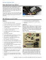
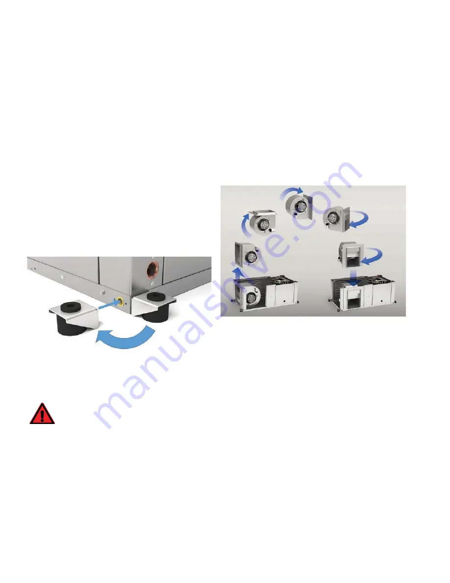
14. Rotate the assembly 180 degrees and turn it 90
degrees, as shown in Figure 4.
15. Slide the assembly into the slot from which you
removed the access panel.
16. Verify that, in its new configuration, the orifice ring
on the blower motor faces the access opening on
the side or end of the unit.
17. Reconnect the wiring to the motor.
18. Slide the access panel into its new location on the
side or end of the unit.
19. Reinstall the unit top, using the sheet metal screws
removed earlier.
Figure 4: Field Conversion of Air Discharge
Piping
Heat pumps are typically connected to supply and return
piping in a two-pipe, reverse-return configuration, which is
inherently self-balancing. It also requires only trim-balanc-
ing where multiple heat pumps with different flow and pres-
sure drop characteristics exist in the same loop.
Supply and return run-outs usually join the heat pump via
short lengths of high-pressure, flexible hose which serve
as sound attenuators for both heat pump operating noise
and hydronic pumping noise. One end of the hose should
have a swivel fitting to facilitate removal for service. Make
sure that threaded fittings are sealed. Teflon tape can be
used to provide a tight seal.
Hard piping is not recommended since it does not
provide vibration or noise attenuation. If used, it must
include a union to facilitate heat pump removal. Avoid
dissimilar metal fittings as they may corrode. If unavoid-
able, use dielectric isolation at the connection point.
Supply and return shutoff valves are required at each
heat pump. The return valve may be used for balancing.
It should have a “memory stop” so that it can always be
closed off but can only be reopened to the proper position
for the flow required.

