HydroBank MS Installation and Operation Manual MAMM-WSHP-IOM-1MSA (October 2014)
7
Horizontal Unit Installation
Horizontal Unit Installation
Unit Location
Do not locate units above noise-sensitive areas such
as offices, meeting rooms, and classrooms. If possible,
avoid locations above areas where there is considerable
traffic as service time may be limited during occupied
hours. Placing units above hallways is a typical location
in schools to avoid potential noise problems, with sup-
ply and return air ducted to adjacent classrooms. Such
locations may limit service time during school hours.
IMPORTANT:
This equipment is designed for indoor
installation only. Sheltered locations such as attics,
garages, etc., generally will not provide sufficient
protection against extremes in temperature and/or
humidity, and equipment performance, reliability,
and service life may be adversely affected.
Suggested Clearances
Units should be positioned to provide clearance to per-
form routine maintenance or service, including easy filter
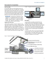
replacement. Figure 1 shows suggested clearances. Any
additional clearances would be beneficial, but are not
always necessary. The requirements on any specific unit
may increase or decrease depending on factors such as
electrical installation codes. If return air is not ducted, be
sure to provide enough clearance for adequate airflow.
Figure 1: Suggested Horizontal Unit Clearances
2 ft (61 cm)
service access
filter removal
(width of filter)
2 ft (61 cm)
motor
access end
discharge
2 ft (61 cm)
motor access
straight
discharge
Mounting
Horizontal units are typically suspended from the
ceiling using four 3/8 inch threaded rods (supplied
by others). The rods should be attached to building
structural members. Slide the rods through the mounting
brackets and rubber isolators provided on each corner
of the unit. The mounts can be repositioned from the
end to the side of the unit to accommodate installation
requirements. See “Repositioning Mounting Brackets”
on page 8.
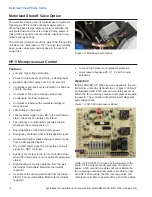
Connect the rods to the mounts using a fender washer
and double hex nuts. The fender washer should cover
the entire bottom of the rubber isolator. See Figure
2. When installed, the unit should be slightly pitched
toward the condensate drain connection.
Figure 2: Typical Horizontal Unit Installation


