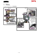
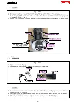
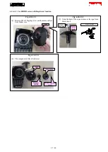
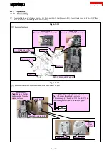
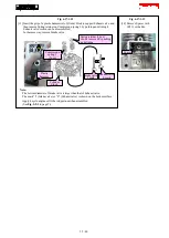

Fig. 6-17-1-3
[4] Remove three M5x14 Hex socket head bolts and Cam
gear cove. Cam gear cover gasket is removed.
M5x14 Hex socket head bolt (3 pcs.)
Cam gear cover
Cam gear cover gasket
Note:
The orientation of the
gasket does not matter.
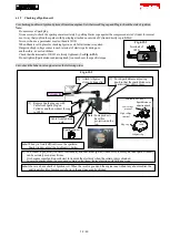
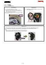
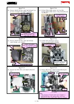
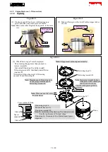
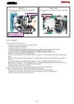
Fig. 6-17-1-4
[5] Pull out Pin 4 and then remove two Cam lifters.
Pull out Pin 5 and then remove Cam gear assembly and
two Rods 2.5.
Cam gear assembly
Pin 5
Pin 4
Rod 2.5 (2 pcs.)
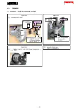
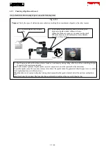
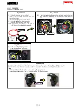
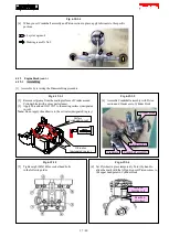
Fig. 6-17-1-5
[6] Remove three M5x16 Hex socket head bolts and
remove Rocker cover complete.
M5x16 Hex socket head bolt (3 pcs.)
Rocker cover complete
Rocker cover gasket
Note:
The orientation of the
gasket does not matter.
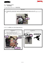
Fig. 6-17-1-6
[7] Pull out Pin 5 with long nose pliers.
Remove two Rocker arm assemblies.
Pin 5
Rocker arm assembly
(2 pcs.)
First push out Pin 5from
this hole with a small
slotted screwdriver.
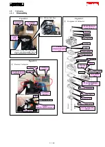
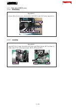
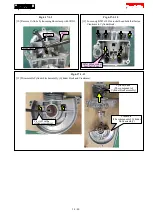
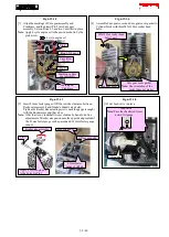
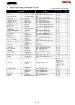
Fig. 6-17-1-7
[8] Remove four M5x14 Hex socket head bolts and Oil
case.
Fig. 6-17-1-8
[9] Remove M4x10 Hex socket head bolt, Retainer plate
and Lead valve. Remove Case gasket.
Oil case
M5x14 Hex socket
head bolt (4 pcs.)
Case gasket
Note:
·
The orientation of front and rear can be checked by
aligning its shape to the mating surface of Oil case.
·
Remove Case gasket residue from the mating surfaces.
Retainer
plate
M4x10 Hex socket
head bolt
Oil case
Cam lifter (2 pcs.)
Note:
common
Lead valve
33 / 40


