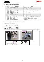
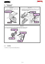
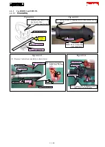
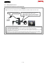

6-4-2-2
Assembling
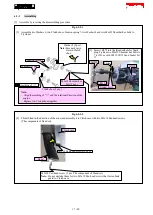
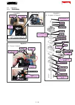
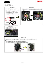
[1] Assemble by reversing the disassembling procedure.
Fig. 6-4-2-2-1
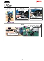
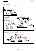
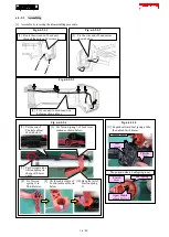
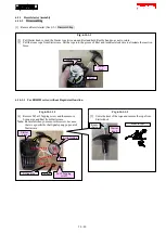
[2] Route the wire end of Lead unit
through the hole on Lever case L.
Fig. 6-4-2-2-2
[3] Fix the wire end of Lead unit as
shown below.
Fig. 6-4-2-2-3
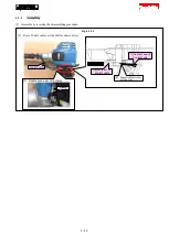
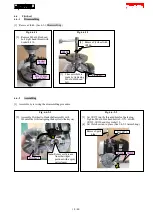
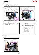
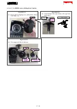
[4] Fix Lead unit to each Lead wire
holder as shown above.
Fig. 6-4-2-2-4
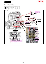
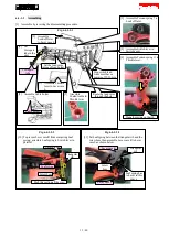
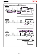
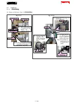
[8] Fix Torsion
spring 11 to
Throttle lever.
[9] Put the cable nipple of
Control cable as shown
below.
[10] Hang the tail of
Torsion spring
11.
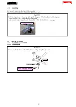
[5] Put the end of
Control cable as
shown below.
[6] Put Torsion spring 7 of Lock lever
section as shown below.
[7] Put Corrugate tube
while aligning its
shape with Lever
case L.
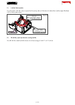
Fig. 6-4-2-2-5
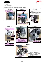
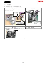
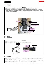
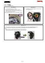
[11] Expand outward Leaf spring a little,
then attach Switch lever.
The position where Leaf spring is set
Switch lever
Throttle
lever
Leaf spring
Switch
lever
Apply Makita
grease FA No.2.
Leaf
spring
14 / 40


