
6-5-2
Assembling
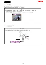
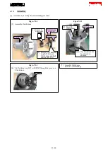
[1] Assemble by reversing the disassembling procedure.
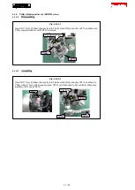
Fig. 6-5-2-1
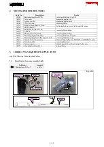
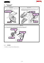
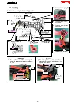
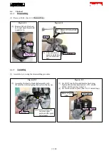
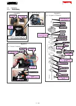
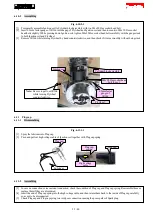
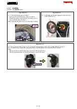
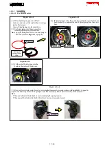
[2] Assemble two Washers 6, two Clutch shoes, Tension spring 7, two Washers 8 and two M6x25 Shoulder hex bolts to
Flywheel.
Washer 6 (2 pcs.)
Tension spring 7
Washer 8 (2 pcs.)
Note:
Face each curve
toward Clutch
shoe.
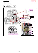
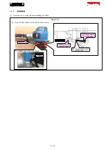
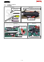
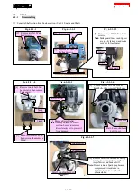
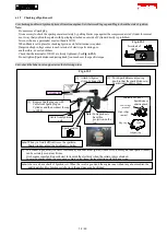
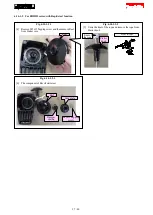
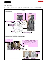
[3] Screw 1R372 into the threaded hole for Spark
plug. Tighten two M6x25 Shoulder hex bolts to
7 to 10N·m with 1R219, 1R220 and Socket bit
13.
1R219
1R220
Fasten
1R372
Socket bit 13
Fig. 6-5-2-2
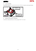
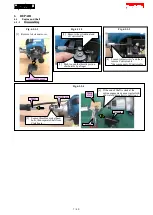
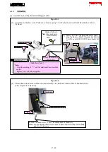
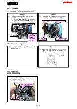
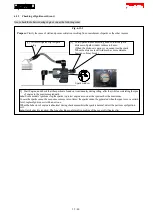
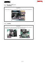
[4] Thrust Stand in the direction of the arrow and assemble it to Clutch case with two M5x14 Pan head screws
(The components of Stand set).
Clutch case
Stand
M5x12 Pan head screws (2 pcs.)
M5x14 Pan head screw (2 pcs. The component of Stand set)
Note:
Do not mistake them for two M5x12 Pan head screws that fasten Tank
guard to Clutch case.
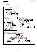
M6x25 Shoulder hex
bolt (2 pcs.)
marking of =>"
Clutch shoe (2 pcs.)
Note:
·
Align the marking of "=>" and the rotational direction of the
engine.
·
Replace two Clutch shoes together.
17 / 40


