
6-5
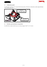
Clutch
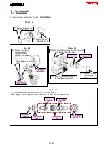
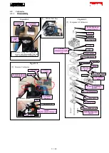
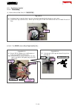
6-5-1
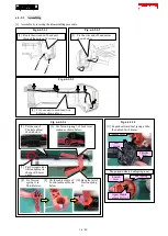
Disassembling
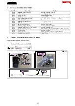
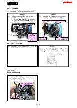
[1] Separate Shaft section from Engine section. (See 6-1 Engine and Shaft.)
Fig. 6-5-1-1-6
Fig. 6-5-1-1
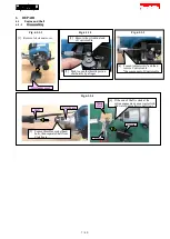
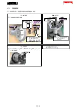
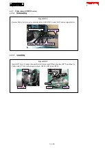
[2] Remove two 5x12 Pan
head screws.
Fig. 6-5-1-1-2
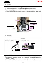
M4x25 Pan head screw (2 pcs.)
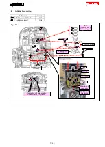
[4] Remove Cylinder cover.
[3] Remove two M4x16
Pan head screws.
Fig. 6-5-1-1-4
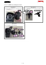
Stand
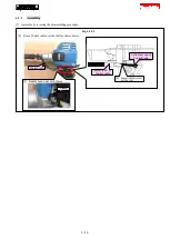
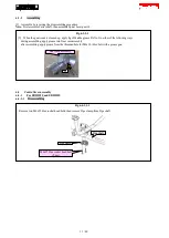
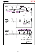
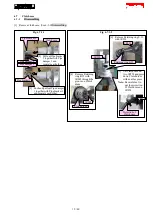
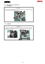
[7] Remove two M5x14 Pan
head screws, then remove
Stand.
[6] Remove two M5x12 Pan
head screws, then remove
Tank guard.
Tank
guard
Fig. 6-5-1-1-5
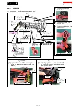
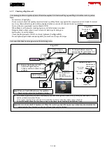
[8] Remove Recoil starter.
Note:
When you remove Clutch
section, be sure to remove
Recoil starter set to prevent it
from damage.
Recoil starter
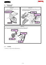
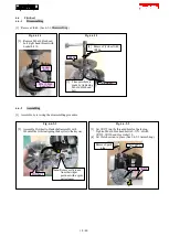
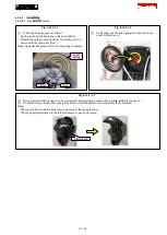
[9] Loosen three M5x16 hex socket
head bolts, then remove Clutch case.
Clutch case
Fig. 6-5-1-1-7
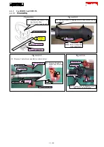
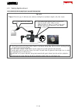
[10] Remove M6x25 shoulder hex bolt by
turning it counterclockwise with an
impact driver and Socket bit 13.
Note:
Do not remove Spark plug because
compressed air resistance in
Cylinder has to be used for the
disassembling.
Socket bit 13
Fig. 6-5-1-1-3
[5] Remove two M4x25 Pan head
screws.
Note:
Tank guard, Starter and Spacer
are jointly fastened, and make
sure not to lose Spacer.
Spacer
Starter
Tank guard
M6x25 shoulder hex bolt
Impact driver
M5x16 hex socket head
bolt (3 pcs.)
16 / 40


