www.maintronic.de [email protected]
17
8.7 Appendix - Symbols
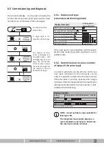
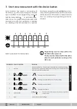
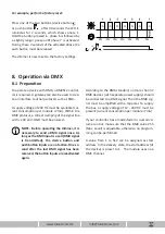
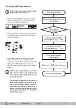
Symbols / legend
Connected load
ON = full brightness
Connected load
dimmed
Connected load
OFF = Off
Device LED
ON = full brightness
Device LED
LED - dimmed
Device LED
OFF = Off
Load type with
leading edge
Load type with
trailing edge
Device button
External push button input
Time for a key press
in this case, press the button for more than 2 sec.
8.6 LED indicator
Operating states are indicated over the LED.
Status LED indicators
Blinking pattern approx. 3 sec.
0s 1,5s 3s
Modulstart INIT
OOOOOOOOOO----------
Once when applying the operating voltage
Standby
O-------------------
During operation with switched off channel
Output Switched On
OOOOOOOOOOOOOOOOOOOO
Switched on, the brightness of the LED depends on the output level
Receive bus event
O-O-----------------
DMX-telegram received
Operation via push button input
OOOO-OO-------------
DMX input button is pressed, mains voltage is present
Programming mode
OOOOO-----OOOOO-----
DMX identification display; ready for load calibration
Error 1
O-O-O-O-O-O---O-----
Switching off outputs due to overload.
Error 2
O-O-O-O-O-O---O-O---
Reduction of output level due to overload.
Fatal Error
O-O-O-O-O-O-O-O-O-O-
Shutdown due to overload or overtemperature
Measuring procedure
O--O--O--O--O--O--O-
Performing calibration with dimming mode
Corridor function activated
OOOOOOOO--OOOOOOOO--
If the corridor mode is activated

