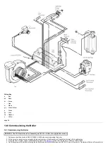

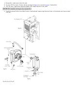
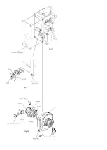
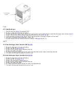


Fig. 50, Fig. 51 & Fig. 52
page 48
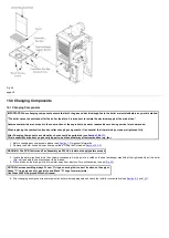
The removal of the fan is necessary to enable the changing of the injector pipe, condensate trap and gas valve (see
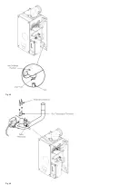
15.7 Injector Pipe (
)
1. Remove the injector pipe by pulling out from the 'O' ring joint in the gas valve.
2. Fit the new injector pipe and reassemble in reverse order.
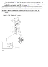
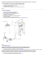
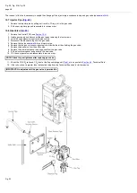
15.8 Gas Valve (
1. Remove the Control PCB (see
2. Isolate gas supply and disconnect the gas tap by removing the four screws.
3. Undo the case pressure pipe from the gas valve.
4. Disconnect the electrical plug from the gas valve.
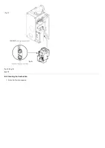
5. Remove the fan (see
) and injector pipe.
6. Remove the two gas valve securing screws from inside the air box holding the gas valve.
7. Remove the gas valve from the airbox side.
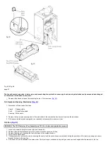
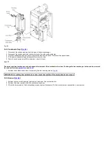
8. Remove the aluminium spacer and its gasket from the gas valve.
9. Fit the aluminium spacer and gasket to the new valve.
10. 1Fit the new gas valve and reassemble in reverse order.
NOTE: Check for gas tightness after replacing gas valve.
11. Check the CO/CO
2
ratio and CO
2
level at the flue sampling point (
) is as quoted in
, 'Technical Data'.
12. If the ratio or level is greater than that quoted, telephone the Technical Enquiries for further advice.
IMPORTANT: No adjustment of the gas valve is permissible.
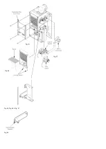
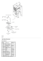
Fig. 53
Содержание Main Heat 12
Страница 8: ...Fig 3 Fig 4 Fig 5 Fig 6...
Страница 38: ...Example 1 Example 2 Example 3...
Страница 40: ...Fig E Fig F...
Страница 51: ...Fig 31 Fig 32 Fig 33...
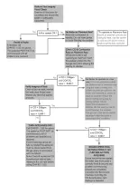
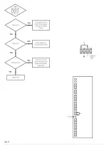
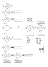
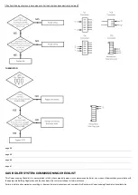
Страница 55: ...Fig 35 Fig 36 page 39 12 2 Checking the Combustion 1 Follow the flow chart opposite...
Страница 56: ......
Страница 63: ...Fig 45 Fig 46...
Страница 66: ......
Страница 69: ...Fig 55 Fig 56 Fig 57 Fig 58...
Страница 72: ...page 52...
Страница 74: ...page 54...
Страница 75: ...DRY FIRE...
Страница 76: ...page 55 IGNITION LOCKOUT...
Страница 77: ...page 56 OVERHEAT LOCKOUT...
Страница 78: ...page 57 FAN LOCKOUT NOTE The fan is supplied with 325 Vdc...
Страница 80: ...warranty This does not affect the customer s statutory rights page 62...
Страница 82: ...page 63...